Introduction to Generator I
| Site: | Plant+ Knowledge |
| Course: | Introduction to the Generator |
| Book: | Introduction to Generator I |
| Printed by: | Guest user |
| Date: | Wednesday, 17 December 2025, 11:03 AM |
1. History of the Generator
In 1831 Michael Faraday discovered the principle of electromagnetic induction. This discovery paved the way for the development of the electric generator. In 1888 Sir Charles A Parsons developed the first ac turbo-generator with his name still synonymous today with the Parsons Turbine manufacturing plant in .
Development continued and by 1922 generator capacities had increased to 20MW (small by today's standards) with the introduction of solid forging and improved construction techniques. In the late 1940's 60MW machines were produced by replacing air-cooling with low pressure hydrogen. Generator output reached 245MW when both stator and rotor conductors were cooled with hydrogen. Further development of water-cooling of the stator conductors along with higher pressure hydrogen cooling of the rotor has allowed construction of 1000MW generators.
2. Principle of Generators
The basic principle of a generator is a magnetic field and an armature assembly with relative motion between the two. Either the magnetic field or the armature may be rotated to produce the electromotive force (emf). Electromotive force is the voltage produced and is measured in volts.
In modern generators it is more practical to rotate the magnetic field (known as the 'rotor') as it is smaller in size, has only two sliprings and operates at a lower voltage therefore requiring less electrical insulation. The armature assembly constructed of a large magnetic iron core and windings (conductors) is the stationary component of the generator and is called the 'stator'.
Small generators usually employ permanent magnets for the magnetic field poles while high output generators will require electromagnetic field poles. The electromagnetic field used in power station generators is constructed of an iron core with wound coils and when direct current (dc) is passed through the coils a magnetic field is created within the iron core causing it to become a magnet.
Electromagnetic Induction
Voltage is induced in a conductor when there is relative motion between that conductor and the lines of force of a magnetic field. The voltage produced is referred to as electromotive force (emf) and is the result of the principle of electromagnetic induction.
The production of an emf by electromagnetic means is the sole purpose of a generator. To achieve this, foundations for the generator design must be developed from the fundamental principles of electromagnetic induction.
For the production of a voltage by electromagnetic means there are three fundamental requirements:
• Magnetic field within the locality of the conductor;
• Relative motion between the conductor and the magnetic field.
Figure 1 shows all three requirements for the production of an emf.
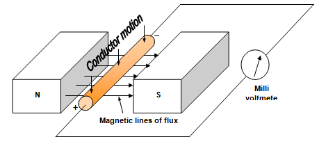
Figure 1: Conductor Moving Down Through a Magnetic Field
The Simple Generator
There are two different designs for generators:
• Rotating field construction.
Figure 2 shows the two different designs for the simple generator. They are both single phase generators; three phase generation will be discussed later in this module.


Figure 2: Two Designs for Simple Generator
In Figure 2(a) the conductor loop is rotated through a magnetic field cutting the magnetic lines of flux. In Figure 2(b) the magnetic field is rotated within the stationary conductor loop causing the magnetic lines of flux to be cut. With both designs the emf is induced in the conductor loop.
Even though the simple rotating field type is the preferred construction for power station generators the rotating armature was the first implemented and we will use it to describe the principles of electromagnetic induction.
Principles of Electromagnetic Induction through the Rotating Armature
When the conductor loop is rotated within the magnetic field of the permanent magnet poles an emf is induced into that conductor loop. A sliding electrical connection is provided in the form of sliprings and carbon brushes to provide a path to and from the external circuit. Individual sliprings are connected to opposite sides of the conductor loop.
If we refer to Figure 2 and use Fleming's right-hand rule for generators it can be shown that:
• Each side of the loop changes the polarity of the emfs that are induced into each half cycle (180 degrees) of rotation;
• Each side of the loop has the induced emf polarities reversed each time they reverse the direction in which they cut the magnetic flux;
• Each side of the loop changes the direction in which it cuts the magnetic flux twice for each revolution – for one half of the cycle it cuts the flux upwards while for the other half it cuts the flux downward.
Note: The sum of the voltages induced into the loop is twice that of a single conductor as the loop is essentially two conductors connected in series, with the instantaneous voltage of each conductor being of equal magnitude and of opposite polarity.
Generation and Magnitude of an AC Sine Wave
With the resultant emf changing direction twice for each 360 degrees of rotation the generated voltage and consequently the output from the sliprings takes the form of and alternating current (AC).
To calculate the magnitude of an emf induced in a conductor cutting a magnetic field of constant flux density at right angles to the flux we use the equation:
e = Blv
Where:
e = instantaneous emf [in volts (V)]
B = strength of the magnetic field [in teslas (T)]
l = active length of conductor (conductor under the influence of the magnetic field) [in metres (m)]
v = velocity of the conductor [in metres/second (m/s)]
Emf's can be induced into a conductor to produce a sine wave if rotation is circular and the density of flux is distributed uniformly. Figure 3 illustrates the production of a single phase sine wave through one complete cycle of a simple two pole generator.
The five instances (a-e) shown in Figure 3 indicate:
• value of emfs that will be induced within the loop after it has rotated through a particular angle.
The sections represent:
a) 0 volts at 0o of rotation
b) e maximum (positive) at 90o of rotation
c) 0 volts at 180o of rotation
d) e maximum (negative) at 270o of rotation
e) 0 volts at 360o of rotation
In each of the sections there are four illustrations; these indicate:
I) position of the loop within the magnetic field.
ii) front cross-sectional view of the loop within the magnetic field.
iii) angle or portion of a revolution in degrees that the loop has rotated within the magnetic field.
iv) direction and the relative magnitude of induced instantaneous emf’s that have occurred at each instant between the start of the loops rotation and its present position.

Figure 3: Single Phase Sine Wave Alternation
Description of Sine Wave Production
A circular path is continually repeated by the loop as it cuts the flux during its rotations within the magnetic field; in this instant it rotates in a clockwise direction. As a result of the path being circular, at each instant of its rotation it will cut the flux at a different angle. Consequently, when the loop moves through the magnetic field at a constant velocity cutting the flux, the rate at which flux will be cut will vary with the size of the angle.
The sine wave is the required output wave form, the name being derived from its sinusoidal shape. To achieve this waveform each side of the loop has to cut the flux at a rate which conforms to sine law. So, the resultant ac waveform is composed of an infinite number of instantaneous values of induced emf with magnitude proportional to the sine of the angle.
The maximum rate of flux change will occur at those angles whose sine = 1 or -1 for each revolution that the loop rotates. Within a two pole field these angles are 90 and 270 degrees.
When either side of the rotating loop cuts the flux at angles of 0, 180 and 360 degrees within the same field system it moves parallel to the lines of force. Ideally, zero flux is cut, resulting in zero induced emf. At other angles the instantaneous value of emf will achieve a magnitude somewhere between zero and maximum in either the positive or negative direction. Each individual magnitude will depend upon the angle at which each side of the loop cuts the flux, and it will be proportional to the sine of the angle.
As a result of the loop rotating in a circular motion within this magnetic field each instantaneous emf (e) induced in each side of a loop is not only dependent an BIv, it is also proportional to the sine of the angle of intersection between the conductor and the flux (sinθ) (θ is the Greek term 'theta' and is used in electrical as referring to angular). As a consequence of this the induced instantaneous emf can now be calculated from the equation e = Blv sinθ.
Calculation of Instantaneous Voltages
Remembering that maximum emf is induced when a conductor is being cut at 900. As the conductor is not always moving at 900 to the magnetic field then maximum emf will not always be produced. Thus giving rise to an expression of voltage:
e = Blv sinθ
Where sin θ is the degree of rotation through the magnetic field as shown in Figure 4.
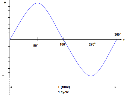
Figure 4: Sine Wave
The value of induced emf compared to the maximum value is calculated by multiplying the maximum value by that fraction of the rotating motion that is the horizontal component.
This fraction is equal to the sine of the angle through which the conductor has rotated.
The calculation of the instantaneous value of voltage or current uses the expression:
e = Vmax sin θ (volts)
Where:
e = the instantaneous voltage in volts
Vmax = maximum voltage in volts (peak voltage)
θ (theta) = angle of rotation in degrees
or
i = Imax sin θ (amps)
where:
I = the instantaneous current in amps
Imax = maximum current in amps (peak amps)
θ (theta) = angle of rotation in degrees
These values may be expressed in either a positive or negative value.
Alternating Waveform Quantities
• Peak to peak voltage
• Cycle
• Period (time taken to complete one cycle)
• Frequency (number of cycles per second)
All these quantities are shown in Figure 5.
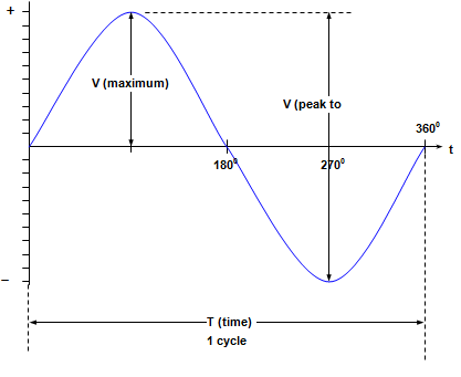
Figure 5: AC Quantities
Expressions relating to time and frequency
T = 1/f
or
f = 1/T
Where:
f = frequency (in Hertz or cycles per second)
T = time (in seconds)
3. Operation of Generators
Generators can be operated in three separate modes:
• Operating alone and supplying a single isolated load (island operation);
• Operating in parallel with other generators to supply a large interconnected power system.
The operating characteristics of generators vary depending on which mode is applicable at the time.
Generated and Terminal Voltage of a Generator
To assist with the explanation of generator characteristics it is necessary to distinguish between:
• Terminal Voltage (ET)
Generated Voltage
Generated voltage is the voltage induced in the stator windings by the action of the magnetic field produced by the rotor when the generator is supplying no load (i.e. open circuit). The value of voltage generated is dependant on the frequency (i.e. rotor speed) and the strength of the rotor field. The amount of rotor current determines the strength of the rotor field. Therefore with a constant speed the generated voltage is dependant on rotor current.
When a generator is supplying load the rotor field is modified due to the effect of what is termed as armature reaction. This armature reaction influences the value of the voltage actually induced in the stator windings. Armature reaction will be covered in detail later in this module.
Terminal Voltage
Terminal voltage as the name suggests is the voltage present at the output terminal of the generator. Terminal voltage is only present when generated voltage is present and is equal to generated voltage only when a generator is open circuited and supplying no load. When the load on a generator is increased the terminal voltage falls below that of the generated voltage due to internal voltage drops. The greatest difference between terminal voltage and generated voltage occurs when the generator is at full load.
Load Characteristic of a Generator
The load characteristic of a generator is defined as the relationship between the terminal voltage and the stator load current with the excitation and speed being kept constant at normal no-load values.
The load characteristic of a generator is best represented by a curve whose shape will vary with the power factor of the load being supplied. Figure 6 shows load characteristic curves for various leading, lagging and unity power factor loads.
Figure 6: Generator Load Characteristic Curves
From Figure 6 you can see that if the load is inductive (lagging) then the terminal voltage will reduce as the load is applied. In this instance it is necessary to increase the excitation as load is applied to maintain the desired terminal voltage. If however the load is capacitive (leading) then as the load is increased so does the terminal voltage. Under these circumstances the excitation will need to be reduced as load is increased so as to maintain terminal voltage.
The behaviour of the terminal voltage of a generator to the load and power factor of that load is attributable to two factors:
• Armature reaction.
Stator Windings Impedance
Due to the resistance and inductive reactance of the stator windings there will be a voltage drop within the generator windings whenever a current is flowing. The value of the voltage drop will depend on the product of the current and the impedance (i.e. E = IZ). Also accompanying this voltage drop is a phase displacement between the generated voltage and the terminal voltage.
Figure 7 shows a circuit diagram representation of a generator on load. The generated voltage (EG) for an ideal generator is reliant on the excitation and assumes the generator of having no impedance. In actual fact there is a component of resistance (R) associated with the stator windings along with an inductive reactance (XL). These components of resistance and inductive reactance have been shown in Figure 7 as a series combination for simplicity. The generated voltage (EG) minus the two series voltage drops will give us terminal voltage.
Figure 7: Circuit Diagram of Generator Load
Effect of Armature Reaction
If the generator is on load and therefore a current flowing in the stator windings another magnetic field is produced around the stator windings. This additional magnetic field rotating in synchronism with the rotor magnetic field affects the rotor magnetic field and is referred to as armature reaction.
This armature reaction either weakens, strengthens or distorts the rotor magnetic field depending on the power factor and load on the generator.
As explained earlier for a given rotor speed the generated voltage EG is dependant solely on the strength of the magnetic field which is governed by the rotor current. When the generator is on no load there is no current flowing in the stator winding and therefore no armature reaction. Under this no load condition the generated voltage is that which is actually induced in the stator windings. When the generator is loaded and armature reaction occurs the voltage actually induced in the stator windings depends on the modified or resultant rotor magnetic field. The generators terminal voltage when on load is therefore not only dependant on rotor current and stator reactance but also the effect of armature reaction.
When the generator supplies an inductive load the rotor field is weakened by the armature reaction and therefore the terminal voltage decreases. Excitation must be increased to return the terminal voltage to the correct value. If the generator is supplying a capacitive load then the rotor field is strengthened and terminal voltage tends to rise above set value. In this case the rotor current is reduced to compensate for the terminal voltage rise. If however the generator is supplying a highly capacitive load such as a lightly loaded long transmission line then the terminal voltage may rise such that rotor current is at minimum and the terminal voltage is still above set value.
Table 1 summarises the effect of armature reaction on the rotor magnetic field for various power factor loads. When armature reaction creates distortion of the rotor magnetic field this takes place in the air gap between the rotor and the stator as the field assumes a position that differs from that of no-load. This distortion of the field causes a reduction in terminal voltage.
|
Type of load on generator |
Power factor of load |
Effect on rotor field |
|
|
Magnitude |
Distortion |
||
|
Pure inductive Resistive-inductive Pure resistive Resistive-capacitive Pure capacitive |
zero lag 0.8 lag unity 0.8 lead zero lead |
weakens weakens slight strengthens strengthens |
none slight yes slight none |
Table 1: Effects of Armature Reaction with Various Generator Loads
4. Generator Construction
The main features of the generator are a rotor surrounded by a two part stator, rotor current collecting rings, known as slip rings, and an assembly of bushings forming the output voltage terminals.
Six high voltage bushings are attached, through terminal plates, to a terminal box located on the underside of the generator collector end. These bushings provide the means for the generator to be electrically connected to the external buses. Each high voltage bushing is internally cooled by the circulation of hydrogen gas.
End shields at either end of the generator stator are of gas tight construction and support the generator bearings and shaft seals which prevent hydrogen gas leaking from the generator.
The entire assembly is gas tight to allow hydrogen gas to be forced through the internal parts for cooling. The stator windings are also cooled by demineralised water.
The generator is of the conventional form for large power stations, with an inner rotating two-pole field and outer fixed conductors. The rotating field is D.C. excited from a static thyristor excitation system.
Excitation current is supplied to the field windings of the rotor from the collector rings. Two semi-circular conductors run through the drilled-out centre of the rotor forging to connect the collector rings with the field windings.
There are four hydrogen coolers, one vertically mounted at each corner of the generator stator.
Resistance Temperature Detectors (RTD’s), thermocouples and stator liquid drains are positioned within the generator assembly for monitoring generator operation.
Current transformers encircle the six individual high voltage bushings to measure the amount of current supplied by the generator and provide protection for the generator. The output of each current transformer is monitored in the Unit Control Room (UCR).
Rotor Cylindrical Construction
Steam turbines operate with greater efficiency when operated at higher speeds. This requirement for a high speed rotor that could handle the greater centrifugal forces led to the introduction of a small diameter cylindrical rotor. As the diameter of the rotor was reduced the length of the rotor had to be increased to maintain the same electrical output.
This cylindrical rotor is constructed as a single forged alloy steel casting into which are machined deep axial slots. These axial slots run the entire length of the rotor and accommodate the rotor windings. A diagram of a rotor forging without any winding conductors is shown in Figure 8.
The winding conductors usually made up of continuous copper strip are insulated and formed into a number of oblong frames of suitable dimensions. Once formed they are laid into the machined slots and then retaining wedges or dovetail keys are driven in from either end to prevent the winding from exiting the shaft when subjected to centrifugal force. Figure 9 shows an enlarged view of a single machined slot with the winding conductor inserted and the retaining wedge installed.
Once the conductors are installed connections to complete the winding are carried out at each end with the start and finish tails being brought out to the sliprings. A cylindrical rotor with rotor windings installed is shown in Figure 10.
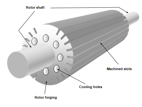
Figure 8: Cylindrical Rotor Forging
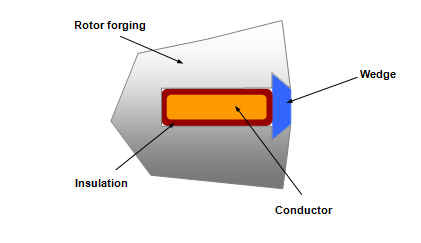
Figure 9: Rotor Machined Slot with Conductor and Retaining Wedge Inserted
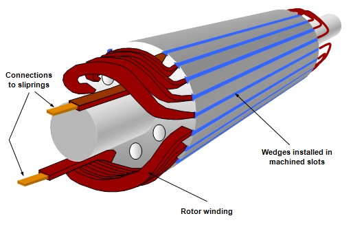
Figure 10: Cylindrical Rotor with Rotor Winding Installed
The rotor windings are suitably supported within the rotors machined slots by the retaining wedges but the section of winding that protrudes each end of the rotor forging need also to be supported. This is achieved by the shrink fitting of retaining end covers or more commonly called end bells. These end bells are normally manufactured from non-magnetic alloy steel and during operation are subjected to high stresses. Dovetail groves are often machined into the ends of these end shields for the provision of counterweights. A rotor showing the end bells installed is shown in Figure 11.
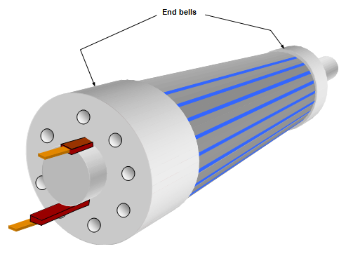
Figure 11: Cylindrical Rotor with End Bells Fitted
Apart from the rotor being constructed of the forging, windings and end bells it also has a shaft with a series of stepped diameters to accommodate:
• Journal surfaces for gas seals;
• Coupling for turbine drive and exciter drive shaft;
• Sliprings;
• Journal surfaces for bearings.
Figure 12: Magnetic Flux Path through Generator
Rotor Cooling
Heat is generated in the windings of the rotor as the dc excitation current flows through the conductors. This heat must be removed because of the temperature limits imposed by the insulating material surrounding these conductors. For this reason and to achieve a high output with a relatively compact machine a forced cooling system is adopted. This forced cooling system may employ air for small output generators or hydrogen for larger generators.
Whether the cooling medium is air or hydrogen the heat extraction process is the same. Cooled air/hydrogen is forced around the outer surface of the rotor as well as through the holes machined in the rotor casting and end bells.
Fan blades installed on the shaft or at the outer ends of the end bells force the cooled air/hydrogen through the rotor where it absorbs heat. The cooling air/hydrogen is then ducted to coolers where the unwanted heat is extracted before it is once again passed through and around the rotor.
Rotor Excitation
The excitation system is the means we use to regulate the voltage output of the generator. When a generator is connected to a large electricity grid and operating in parallel with a number of other generators a variation in the excitation which causes an increase or decrease in rotor field current causing a change in MVar or reactive power output of the generator. Provided normal excitation conditions are established the megawatt or real power output of a generator is entirely dependent on the input power to the steam turbine (i.e. steam conditions)
Excitation current is regulated to maintain a generator terminal voltage to suit power distribution system requirements under changing conditions.
The excitation system consists of a number of components:
• Automatic voltage regulator;
• Rectifier/s;
• Main exciter;
• Sliprings;
• Rotor field.
The excitation system starts with the pilot exciter which usually has a permanent magnet rotor. In some cases the pilot exciter has an electromagnet type rotor which is excited with dc from the station batteries.
The pilot exciter is connected to the same shaft as the main exciter and generator and this can be seen in Figure 13. This common shaft is rotated at 3000 rpm for 50Hz output and 3600 rpm for 60Hz output.
The electrical current produced by the pilot exciter is passed through the automatic voltage regulator (AVR). The AVR regulates the input excitation to the main exciter depending on generator output demands. Output from the main exciter is then rectified prior to being passed through the sliprings and into the rotor windings.
The AVR is installed in the system immediately after the pilot exciter as lower currents are present at this location and therefore permitting the AVR to be a cheaper and more compact unit.
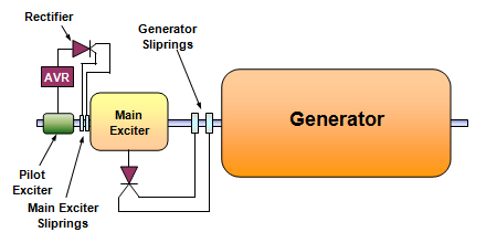
Figure 13: Simplified Diagram of Excitation System
Automatic Voltage Regulator (AVR)
The AVR is the device that regulates the terminal voltage of the generator. It can be operated in manual control (not recommended and only used in emergency) and fully automatic control (preferred mode).
There are a number of different methods employed to carry out the function of the AVR but the result is the same for each case. A simplified method of operation is shown in Figure 14.
The operating principle of the AVR shown in Figure 14 is as follows:
The electrical output from the pilot exciter is firstly rectified. It is then passed through the resistance bank and beam balance to the positive slipring of the main exciter. The negative slipring is connected directly back to the pilot exciter.
As the terminal voltage of the generator increases the voltage sensed by the VT increases. This causes the current flowing through the beam balance operating coil also to increase. With this increase in current in the operating coil the magnetic strength increases and attracts the beam balance towards it. As this happens the contacts on the beam balance move in a clockwise direction to the next terminal thus increasing the resistance in the circuit to the main exciter sliprings. This causes a reduction in excitation strength to the main exciter and then the generator rotor, which, in turn, reduces the generator terminal voltage.
Conversely if the generator terminal voltage falls the operating coil has less magnetic attraction and the beam balance moves in an anti-clockwise direction under the influence of the spring attached to the beam balance. The causes the beam balance contacts to move to the next terminal and reduce the resistance in the circuit. With this reduction in circuit resistance the circuit current increases causing an increase in excitation in the main exciter and generator rotor causing the generator terminal voltage to rise.
After either an increase or decrease the system will find a point of equilibrium and remain at that point unless the generator terminal voltage is changed by system requirements or adjustment of the set point.
The set point for generator voltage is adjusted on this system is by rotating the knurled knob to either increase or decrease spring tension on the beam balance.
This explanation of how an AVR operates is an exceptionally simple one and is not used on modern generators but the principle is the same. Modern AVR’s are fully electronic and have increased features and redundancy incorporated into them for greater reliability.
Figure 14: Simplified AVR
A later trend in excitation control is to eliminate the pilot exciter and main exciter completely and substitute these with a static excitation system consisting of an excitation transformer, automatic excitation regulator (AER), pulse amplifier (PA) and thyristor rectifier. A simplified diagram of this system is shown in Figure 15.
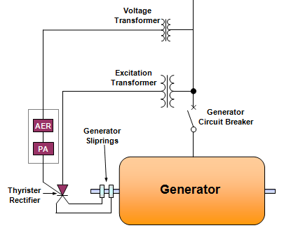
Figure 15: Simplified Diagram of an Automatic Excitation Regulator
The advantage of this system is that it is cheaper and has no moving part; but the disadvantage with is that excitation power must come from the electrical grid and therefore black start ability is not available.
Brushless Excitation
Some generator manufacturers offer a brushless excitation system. A diagram of this system is shown in Figure 16 and a description of operation follows.
With brushless excitation the pilot exciter is a normal permanent magnet rotor construction. The AVR is installed in the same location as for slipring construction but the main exciter is constructed with the main field as the stator and a three phase wound rotor. Installed in the shaft is a set of rectifiers that supply the generator rotor with dc excitation.
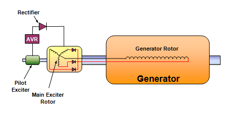
Figure 16: Brushless Excitation
Stator Construction
The stator of a large modern generator is constructed of three main components:
• Iron Core
• Windings
Outer Frame
The outer frame is of welded steel plate construction. It is rolled and welded to form a cylindrical shape and is gas tight. Depending on whether the generator is either hydrogen or air cooled will determine the actual construction strength. For air cooled generators a lighter construction is employed as this type of generator only operates slightly above atmospheric pressure where as a hydrogen cooled generator operates at 300-400kPa above atmospheric pressure. The construction technique is the same for both only more robust for hydrogen cooled generators to accommodate the greater pressure. A diagram of an alternator stator is shown in Figure 17.
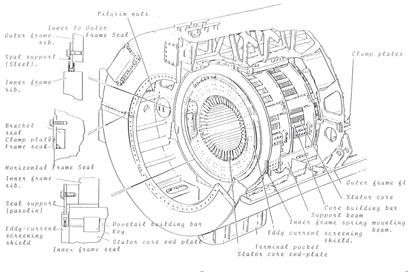
Figure 17: Outer Frame of a Generator
Iron Core
The iron core contains the stator windings (conductors) and is of laminated construction. A number of thin (approximately 0.5mm) high quality silicon steel laminations are assembled together to form a segment. Many segments separated by spacers (to allow for cooling) are then tightly clamped together with end plates to complete this iron core. The clamping end plates are of a non-magnetic construction so as not to become part of the flux path.
Attachment of the iron core to the outer frame is by means of spring plates. These spring plates dampen out frequency vibrations generated in the iron core being transmitted to the outer frame.
Windings
Insulated stator conductors are tightly packed into the longitudinal slots of the laminated iron core and secured with wedges. Overhanging coil ends are lashed down with insulating material to insulating blocks bolted to the iron core end plates.
Both ends of each phase of the stator windings are brought out to the generator terminals, which can be situated on either the top or bottom of the outer casing (depending on manufacturer). Three of these terminals form the three phase conductors that connect to the generator transformer. The other three terminals are connected together to form the neutral or star point of the generator.
The stator conductors are formed into a coil to make up each phase and can be either solid construction (low output generators) or of the hollow tube construction (high output generators). A solid type construction is shown in Figure 18 while a hollow tube type is shown in Figure 19.
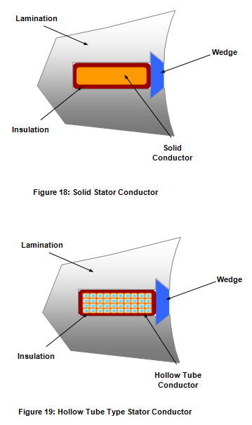
The benefit of a hollow tube type conductor is that a cooling fluid can be passed through the centre of the individual conductor to remove unwanted heat. With this type of construction the physical size of the generator can be greatly reduced whilst maintaining the megawatt output.
Bearings and Lubrication
The rotor shaft is supported by two white metal journal bearings similar to that used on the turbine rotors. These horizontally mounted bearings are of a split type construction and bolted to the endplates of the outer casing. All joints are gas tight and the bearings are insulated to stop the flow of induced shaft current through the bearing surfaces. If these induced shaft currents were allowed to flow through the bearing faces they would be extensively damaged by pitting caused by electrical arcing.
Lubricating oil for the bearings is supplied from the turbine lubricating oil system and jacking oil systems. For more information about these systems refer to the turbine manual of this series.
Prior to placing the generator and turbine on turning gear the rotor must be lifted by the jacking oil system to create a layer of oil sufficient to prevent any contact between the white metal bearings and the rotor shaft. For more information about this system refer to the turbine manual of this series.
The exciter and pilot exciter bearings also receive lubricating oil from the turbine lubricating oil system but are not supplied with jacking oil due to their significantly lighter construction.
5. Generator Cooling
A generator operates with a high magnetic field and a high current density producing unwanted heat, due to copper losses in the conductors (both rotor and stator) and due to iron losses in the iron core. This heat must be removed or the insulation will be damaged and failure of the generator will occur. As the size of the machines increases so too does the amount of heat generated and requiring to be dissipated.
Industry standards define the maximum allowable temperatures for stator and rotor windings, and these standards tend to limit the size of the generator, dependent on their means of cooling.
In order to produce generating sets with a high power output and a relatively compact construction, manufacturers have been forced to devise more effective cooling systems.
Generator Hydrogen Cooling and Supply System
Characteristics of Hydrogen as a Cooling Medium
Around 1937 hydrogen became the cooling gas universally used in larger machines. Compared to air, hydrogen has a relative specific heat that is 14 times better and a relative density that is 4 times less. In addition, pressurised hydrogen is a better insulator than air, and hydrogen is not an oxidising agent. Helium was considered for cooling but its relative specific heat is only 5 times better than air and its cost is five times more than hydrogen. Helium gas is not available in abundance. There is a concern for hydrogen fires which air and helium does not have. However, in a nearly pure state (>90%) hydrogen does not support combustion. With proper operation, fire hazards are all but eliminated as evidenced by the operating record of utilities in the
The function of the Hydrogen Gas System is to provide high purity, dry hydrogen gas to act as a cooling medium within the Gas Turbine Generator Frame.
Hydrogen gas has a higher thermal conductivity and heat transfer coefficient than air but a much lower density, (7.00:1 1.35:1 and 0.07:1 against air in each case) therefore it acts as a much better heat transfer medium than air when applied to cooling the internal components of the generator.
In addition, pressurized hydrogen is a better insulator than air, and hydrogen is not an oxidizing agent.
The heat transfer capability of the hydrogen gas is increased if the mass of the gas is increased for a given volume. The gas is therefore normally supplied to the generator at a pressure of between 200 to 400 kPa.
Hydrogen Gas Safety
In considering hydrogen as a cooling medium there was a concern for hydrogen fires, a concern, which air and helium did not share.
Helium was considered for cooling but its relative specific heat is only 5 times better than air and its cost is five times more than hydrogen. Helium gas is not available in abundance.
It was considered that, providing adequate safety precautions were maintained, hydrogen could be used effectively in an enclosed cooling system.
Hydrogen Gas forms an explosive mixture with air in concentrations between 5% and 70% Hydrogen.
The intensity of the explosion caused by ignited hydrogen/air mixture varies proportionally, having zero values at 0% and 70% Hydrogen.
The actual pressure of the gas mixture also affects the intensity of an explosion should one occur.
To ensure that a condition does not occur that will create a possible explosion and to reduce the intensity of the explosion, should one occur, the following precautions must be carried out:
• During the purging phase the pressure within the generator frame is decreased to 10 to 20 kPa.
Components of the Hydrogen Gas System
The components of the Hydrogen Gas System include the following:
• Hydrogen Dryer
• Gas Pressure/Purity Monitoring Unit
• Carbon Dioxide Supply
• Supply and Vent Valves and Pipework
• Hydrogen Circulating Fan
• Water/Oil Leakage Detectors
Hydrogen Gas Supply
A makeup supply of hydrogen gas must be available to the hydrogen cooling system to allow the pressure and purity of the hydrogen gas to be maintained while ever the generator is in service and/or filled with hydrogen.
Makeup supply is normally taken from storage banks of compressed hydrogen bottles connected to supply manifolds.
The storage bottles themselves may be replenished by an external supplier or refilled from hydrogen generating plant located on site.
The supply pressure from the hydrogen bottles to the alternator frame may be automatically regulated by a manually set pressure regulating valve or, alternatively, by a reducing valve provided in parallel with the pressure regulating valve.
The pressure of the storage bank and the pressure downstream of the pressure reducing station are normally monitored.
Hydrogen Gas Dryer
The dewpoint of hydrogen within a generator is normally maintained in the order of –25° C in order to prevent internal moisture generated corrosion and failure. This would normally necessitate the inclusion of a hydrogen dryer as part of the hydrogen system.
A number of types of dryer are available in the industry, heatless, regenerative dryers, desiccant dryers, and refrigerant dryers. Any one of these could find an application as a hydrogen dryer.
Within the generator frame, the hydrogen circulating fans create areas of low and high pressure at their suction and discharge respectively.
By locating the hydrogen dryer supply and return pipework between the high and low pressure sections of the generator frame a gas flow is induced through the dryer whenever the alternator shaft is rotating at synchronous speed and the shaft mounted circulating fans are in operation. Unless a dedicated circulating fan is incorporated into the dryer circuit drying cannot take place with the generator out of service.
Maintaining Hydrogen Gas Purity
Maintaining hydrogen gas purity is of paramount importance and the purity of the hydrogen gas within the generator frame is normally monitored by passing a sample of the gas through an analyser.
As carbon dioxide is used as an interfacing agent when gassing up and degassing the generator, it is most common for the analyser to have several functions and to be able to monitor hydrogen purity and the concentrations of hydrogen and carbon dioxide in air.
The suction side of the analyser can therefore be connected to either of two suction lines, one taken from the upper portion of the generator and used for hydrogen purity analysis during hydrogen filling ,the other, taken from the bottom section of the generator and used for analysis of the gas purity while CO2 is being used as an interfacing medium between hydrogen and air.
During normal operation the lower detection point should be used as lower purity hydrogen will tend to be more dense than high purity hydrogen and a reduction in purity should be evident first in the lower portion of the frame.
Although different limits may be placed on purity at different power station sites hydrogen purity should be maintained above 93%.
During normal operation of the generator the small amount of seal oil migrating into the generator frame may carry some entrained air and moisture with it. This air and moisture will be released from the seal oil as it migrates to the defoam tank and will eventually cause a deterioration in hydrogen purity. In order to maintain hydrogen purity it may be necessary to bleed off a portion of the gas while making up the gas volume with pure hydrogen from the cylinder bank.
In some installations a constant, regulated bleed is maintained through bleed lines directed to atmosphere through a flow regulating valve, an oil mist separator and a flowmeter.
Carbon Dioxide Supply
Carbon Dioxide is used as an inert interfacing agent when filling the generator frame with hydrogen or air.
The Carbon Dioxide Supply usually consists of banks of storage cylinders attached to a supply manifold. The storage cylinders may be replenished by an external supplier or by a bulk carbon dioxide facility within the station site.
It should be noted that the gas discharge pipework temperature can be below freezing point and contact between skin and the pipework may result in the skin freezing to the pipework causing frost bite injury to the affected area. Appropriate safety precautions should be taken during operation of this equipment.
During purging the introduction of carbon dioxide may be allowed to cease once the carbon dioxide reaches a purity <75%. The detection of carbon dioxide purity must be taken from the upper sampling point in the generator frame.
Hydrogen Gas Cooling Circuit
The hydrogen cooling circuit includes paths through the stator and rotor windings (see previous diagram of air cooled circulation paths) where heat is gained and a path through the hydrogen coolers where heat is dissipated. To ensure a positive flow through the circuit two fan impellers are mounted on the generator rotor shaft and each draws a portion of the hydrogen from the cooler and passes it through the generator windings and back to the windings. This circuit creates a high and low pressure area within the generator frame while ever the machine is operating at rated speed.
The hydrogen dryer takes advantage of the two different pressure zones to establish a hydrogen flow through the drying chamber.
Banks of hydrogen coolers are normally provided at the side or top of the generator frame. The cooling medium is normally high quality demineralised water from a closed cooling water system.
Contamination of the Generator frame can occur due to a failure of the hydrogen coolers, causing a water leak into the frame, or failure of the hydrogen shaft seal allowing oil ingress into the frame. In either case leakage must be detected. Detection points are normally tapped into the generator frame at each end of the generator adjacent to the seals. These detectors should be regularly checked and the quantity and type of liquid found in them should be logged.
System Monitoring and Alarms
The following parameters associated with the hydrogen gas system would normally be monitored:
• Hydrogen Gas Purity
• Hydrogen Gas Pressure
• Hydrogen Supply Bank Pressure
• The Amount of Lliquid within Liquid Detectors
Hydrogen Sealing System
The generator rotor shaft ends of a hydrogen-cooled generator must be brought out of the gas tight enclosure therefore some means must be provided to prevent the escape of gas along the shaft. This function is provided by a hydrogen shaft sealing system, the components of which normally consist of:
• Seal Oil Ssupply System
Sealing Mechanism
Several propriety seal designs are available on the market. These tend to belong to two categories: one of which forms a seal directly against the shaft, the other forms a seal against a face of a collar machined on the shaft.
In both designs, oil is used to place an hydraulic force on the seal, forcing it against the shaft or collar, while at the same time a film of oil is forced into the fine clearance between the seal and the shaft or collar to act as a lubricant and to remove heat generated at the seal face.
The positioning of the seal means that one side is subjected to the pressure exerted by the hydrogen within the alternator frame while the other is normally located within the adjacent bearing housing and as such is subject to the slightly negative pressure exerted on the bearing pedestal. This pressure gradient across the sealing face has the effect of allowing the greater amount of seal oil to pass from the seal face to the bearing housing. A much smaller flow passes through to the generator side of the seal and into the alternator frame.
In seal designs employing a seal ring and shaft collar two oil supplies are provided; annulus oil and face seal oil.
Annulus oil is directed into an annulus in the seal ring and acts as a hydraulic force to drive the seal against the shaft collar. It is important that the annulus oil is supplied first when setting up the seal oil system in order to ensure that the sealing faces mate around the entire seal circumference. If the ring is slightly skewed excessive oil flows will be seen at the seal face. Although the annulus oil is predominantly a hydraulic medium a small flow is allowed to be bled from the annulus to prevent overheating of the oil at the seal.
As the function of the annulus oil is to maintain a hydraulic force on the seal its pressure is regulated to maintain a set positive differential between itself and the hydrogen pressure within the alternator frame (Annulus Oil pressure > Hydrogen pressure). Annulus oil pressure will therefore vary considerably during periods when the gas pressure is allowed to increase or decrease.
The Face Seal Oil is used as a lubricating and heat dissipation medium. The pressure of the face seal oil is constant.
In seal designs employing a seal directly against the face of the shaft a single oil supply is provided. This supply acts both as the hydraulic medium and the lubricant for the seal. As such this oil supply is regulated to maintain a set positive differential between itself and the hydrogen pressure within the alternator frame.
Figure 20: Typical Seal Design Employing a Seal Directly Against the Shaft
Seal Oil Supply
The function of the seal oil supply is to provide moisture and contaminant free oil at a regulated pressure to the hydrogen seals.
The oil used in the seal oil system is generally drawn from the main lubricating oil system with the pumps either drawing directly from the main lubricating oil tank or from a separate seal oil tank taking its initial and make-up supply from the main oil tank.
The need to maintain the seal oil system in service while ever hydrogen gas (or Carbon Dioxide) is contained within the alternator frame demands that the seal oil pumps must be provided with a degree of redundancy. This usually means that an ac motor driven pump is provided for normal and standby duty while a dc driven pump is provided for emergency.
The seal oil pump discharge is regulated, as required, to maintain the pressure above the design maximum hydrogen gas pressure allowable within the alternator frame.
In designs demanding a separate annulus and face seal oil pressure the face seal oil pressure is regulated at a constant pressure while the annulus oil is regulated to maintain a positive pressure differential over the hydrogen pressure.
Prior to reaching the shaft seal the seal oil passes through a heat exchanger dissipate heat from the system and to maintain a set oil supply temperature (changes in oil temperature and viscosity will effect the performance of the seal).
A filter is provided in the seal oil supply line to remove particulate contaminants.
Seal Oil Return
The oil returning from the seals takes two independent paths, the majority returns through the bearing side drain while a minor amount returns from the hydrogen or generator frame side of the seal.
Oil returning from the bearing housing side of the seal passes to a loop seal oil tank before returning to the seal oil pump suction side (or main oil tank). A vapour extraction fan is connected to the loop seal to maintain the bearing housing under a negative pressure and to remove any oil vapour or hydrogen present within the bearing housing.
The oil returning from the alternator side of the seal may have hydrogen gas entrained within it, therefore this oil is passed first to a defoam tank before it is allowed to mix with the oil returning from the bearing side of the seal.
The function of the defoam tank is to allow the small quantity of oil returning from the frame to settle for a period of time during which the hydrogen gas is detrained from the oil. The flow of oil from the defoam tank is regulated to maintain a constant level of oil within the tank. This is done to form a seal between the alternator frame and the seal oil pump suction pipework. Should the seal within this tank be lost the frame can connected to atmosphere through the loop seal oil tank and associated vapour extraction fan resulting in a major loss of hydrogen to atmosphere.
Liquid Detectors
Should the shaft seal face be damaged, allowing excessive flow of oil to the hydrogen side of the seal a condition could exist in which oil overflows from the internal drainage system to the alternator frame.
Liquid detectors with alarm contacts are fitted to the lower sections of the alternator frame to initiate an alarm should a quantity of oil or water be detected.
Seal Oil System Monitoring and Control
Devices within the seal oil system normally monitor the following:
• Seal oil pump discharge pressure
• Seal oil to hydrogen differential pressure;
• Seal oil supply pressure pressure to each seal (face and annulus on ring and collar type seals);
• Seal oil temperature at the cooler exit;
• Seal metal temperature;
• Defoam tank level;
• Vapour exhaust fan suction pressure (vacuum gauge).
The seal oil system should be placed in service before hydrogen is admitted to the alternator frame and must be retained in service until the frame is degassed to atmospheric conditions. The seal oil system should also be placed in service before the turbine/generator is rotated on barring gear.
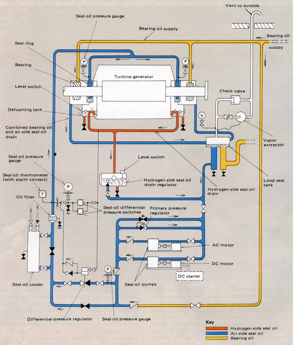
Figure 21: A Typical Seal Oil System
Stator Water Cooling
As the output rating of generators increases so the use of water cooling for heat removal in the stator becomes more effective. Stator Water Cooling is additional to the cooling still maintained by hydrogen circulation around the stator and through radial cooling passages within the stator.
In a water-cooled stator, demineralised water is circulated through dedicated pathways built into the stator laminations. The stator cooling circuit passes through the entire length of the stator and is connected to the stator water supply and return manifolds through insulated hoses (PTFE or other suitable plastic).
The stator water system usually consists of the following components:
• Filters;
• Coolers;
• Flow measuring equipment;
• Conductivity monitoring equipment and demineralising unit;
• Stator water head tank and associated pipework.
Stator Water Pumps and Circuit Components
The stator water cooling system is critical for maintaining the generator within the limits of design operating temperatures and would normally demand redundancy in its pumps.
Pumps are usually ac motor driven centrifugal pumps discharging at a head pressure slightly lower than that of the hydrogen pressure contained within the generator frame. This has the effect of allowing gas to leak into the stator water system rather than permitting stator water to migrate into the generator frame.
Small and insidious amounts of hydrogen gas entering the cooling water circuit may be detected by the incorporation of float chambers above the generator inlet and outlet manifolds and at the pump suction. Float operated alarm contacts are made when a set volume of gas displaces the water in the chamber. The frequency of alarms and the amount of gas vented from the system to clear the alarm aids in determining the size of the leak.
Heat from the Stator Water System is dissipated to atmosphere through a heat exchanger. Usually the heat exchangers use lower quality cooling water as the cooling medium. The supply pressure of the auxiliary cooling water is lower than that of the stator water system to reduce the likelihood of stator water contamination if a leak in the heat exchanger occurs.
Stator Water Flow and Conductivity Measurement
In order to monitor the stator water systems performance it is common to include of flow measuring station and a differential pressure monitoring station, which detects leakage within the generator frame and initiates a trip of the generator.
The quality of the demineralised water must be high to prevent current flow through the system. Metal pickup from the stator pipework can result in an increase in conductivity with time. The conductivity of the stator water is normally monitored and the provision of a mixed bed polishing column allows the conductivity to be maintained within design limits.
Phase Isolated Bus (PIB)
A Phase Isolated Bus – PIB (or Isolated Phase Bus - IPB) is one in which the conductors of each phase are enclosed in a separate enclosure (normally tubular) and separated from the adjacent phase conductor enclosure by an air gap.
The enclosures are usually made of rigid metal and the conductors within are carried on insulators to maintain safe clearances.
The enclosures may be served by a system, which provides filtered, dry air as a cooling medium and as a means of pressurising the enclosure to prevent the ingress of dust and moisture.
Phase Isolated Busbars are normally used to provide a conduit to carry the conductors from the generator terminals to the unit or generator transformer.
Figure 22: Phase Isolated Busbars Being Erected on Site
6. Generator Capacity or Performance Diagram
When operating a generator we must consider conditions which impose limits on the loading of the generator. Information is often provided in the form of a tabulation which gives for instance permissible megavar (MVar) loading for a particular megawatt (MW) load on the generator. In is however more convenient to provide this information in the form of a generator capability performance diagram.
The conditions that impose limits on generator loading and the reason for the limit are shown in Table 2 below.
|
Limiting Condition |
Reason for Limit |
|
Stator current MW Load Rotor angle Rotor current |
Stator temperature rise Turbine characteristics Generator stability Rotor temperature rise |
A complete capability diagram will now be developed by considering in turn each of the operating limits described in Table 2.
Multiplying stator current by rated generator voltage gives us a mega volt-ampere (MVA) limit for the generator. This information is diagrammatically shown in Figure 23 which is known as a simple circle diagram for a generator.
The diagram shown in Figure 42 can also be considered as a generator capability or performance diagram which in this instance only takes into account the stator current or MVA limit and ignores all other operating limits imposed on the generator. Provided that the MW and MVar load on the generator coincides with a point falling anywhere within the confines of the diagram the stator current (and MVA) limit of the generator will not be exceeded for normal rated voltage conditions.
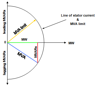
Figure 23: Generator Capability Diagram (showing MVA & stator current limit only).
Figure 24 shows the generator capability diagram now modified to take into account the MW load limit due to the power available from the turbine.
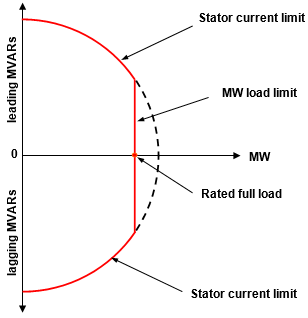
Figure 24: Generator Capability Diagram (showing stator current and MW load limits).
Rotor angle and stability limit is reached only when the generator is operating at a leading power factor and importing MVars. This theoretical stability limit corresponding with a rotor angle of 90o is now incorporated and shown in Figure 25. The limiting value of leading MVars for a rotor angle of 90o depends on the design of the generator but is usually around two thirds of the maximum MW load (i.e. a 60 MW generator would have a MVar capability of approximately 40MVars).
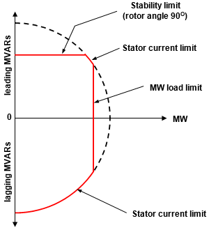
Figure 25: Generator Capability Diagram (showing stator current, MW load and stability limits
The final limiting condition to be considered is rotor current limit. Rotor current limit is reached when the generator is producing considerable MVars to supply a lagging power factor and under these conditions rotor excitation is at a high level. Figure 26 shows a capability diagram in which there is a small area where the limiting factor is stator current but a large area relating to rotor current limit. With some generators there is no stator current limit when the machine is operating on high excitation and this is shown in the capability diagram of Figure 26.
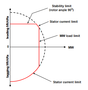
Figure 26: Generator capability diagram (showing the four limiting conditions).
The capability diagram of a typical 60MW generator is shown in Figure 26 Lines are drawn on the diagram showing rotor angle and power factor for various loading conditions for the generator. Also shown are three stability limits; one for when the excitation is on automatic voltage control (AVR) which permits operation beyond the theoretical stability of 90o, one showing the theoretical stability limit and the other for when the excitation is on hand control and it is necessary to incorporate a stability margin of safety.
In Figure 27 it can be also seen that the stator current limit is reached only at high leading MVar loads and that the rotor current limit is the only restriction on lagging MVar loads.
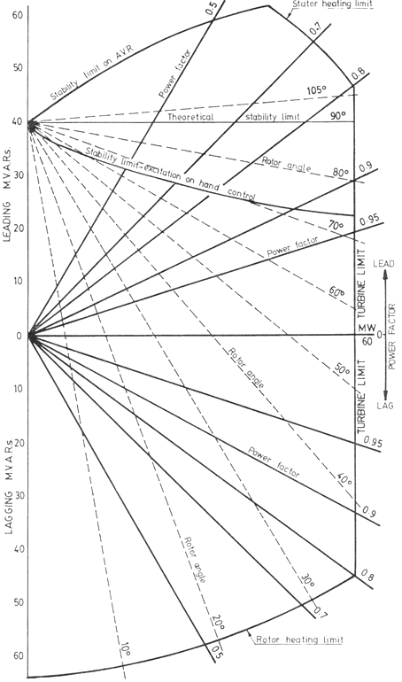
Figure 27: Capability Diagram for a 60MW Generator.
It should be remembered that the limiting conditions shown on a capability diagram apply only for normal rated voltage.
While the capability diagram is a useful guide to generator operation (particularly in the leading power factor region), it is important that full reliance should be place on the available generator instruments such as ammeters, rotor angle indicator, temperature indicators and alarms to ensure that specified limits are not exceeded.
7. Synchronising and Parallel Operation of AC Generators
Control of the Generator Preparatory to Synchronising
There are several requirements that must be satisfied before a unit can be synchronised to the system.
They are:
• Phase angle between the incoming generator and the system must be matched;
• Frequency of the incoming generator and system must be the same;
• Incoming and system must have the same phase rotation.
Operators have control of the first three of these requirement and we will now discuss these in detail.
Control of Voltage
The voltage of the incoming supply (generator terminal voltage) is regulated once the generator field switch has been closed and the excitation adjusted. The field switch is often closed during the run up period at approximately 90-95% normal rated speed. It is good operating practice to always have the excitation control system set at minimum position whenever the field switch is closed to avoid any risk of over-voltage. It is normal practice once the field switch is closed that the AVR be selected auto and the terminal voltage set point adjusted to meet synchronising requirements.
The voltage of the generator increases as the speed increases and the synchronising voltmeter should be observed to check that the AVR is maintaining the required set point value. A final adjustment of voltage may be necessary when the unit is running at synchronous speed.
NOTE: As the impedance of the generator transformer is primarily the component of inductive reactance it is critical that the speed of the machine does not go below a predetermined value as with low speed we get low frequency and this can cause overfluxing of the generator transformer. Overfluxing is when a transformer draws excessive magnetising current.
Control of Frequency and Phase Relationship
When the speed of the turbine is within range of the governor, the frequency of the incoming supply can be regulated on the speeder gear. The speeder gear should have been set to minimum before the run‑up so that control can usually be exercised once the speed exceeds approximately 2850 rpm.
When the generator is running close to normal speed as indicated on the tachometer or frequency indicator or recorder, the synchroscope can be energised. The operating range of the synchroscope is fairly narrow and it should not be energised until the speed is close to normal. When the frequency of the generator and the system is the same, the pointer of the synchroscope will remain stationary at some point around the dial.
The phase relationship between the incoming supply and the system is varied by momentarily changing the generator frequency. If the generator is running steadily at a frequency which is close to but not quite equal to the system, the phase relation between the two will be slowly changing all the time. The synchroscope pointer will rotate at a speed proportional to the difference in frequencies, and the position at any instant indicates the instantaneous phase relationship, between the incoming supply and the system. For example, at 12 o'clock, they are in phase, at 6 o'clock, 180o out of phase.
Infinite Busbars
In some respects, a large distribution system can be considered as a large mechanical flywheel. Each generator contributes its share of energy to keep the flywheel rotating at constant speed while the electrical load on the system acts as a brake, tending to slow the fly wheel down. When the capacity of the system is very large, changes in conditions on one of the generators may have little or no perceptible effect on system conditions.
An individual generator connected to a system which in comparison may be regarded as infinitely large, is said to be operating on "infinite busbars". Such a system is essentially a source of voltage and frequency, both of which remain. substantially constant.
Except for large variations in the conditions on a generator, the state distribution system closely approaches the concept of infinite busbars. Although changes actually occur on the system when the speeder gear or excitation is varied on a generator, the effect frequently is so small that it is not noticed on the control room instruments.
For example, if a system, having multiple generating sets operating in parallel to supply a load of 8000 MW, was deprived of 350 MW to 400 MW of generation, the frequency would fall significantly by approximately 0.1 Hz. Should this reduction in generation be confined to the loss of a single generator, however, there would be only a small change in system frequency because the governors of the remaining generating units would automatically increase their output. In the same way, the AVR's on these units would automatically compensate for the lost MVar output of the lost unit so that the system voltage will remain practically unchanged.
Stable Operation of Generators Operating in Parallel
Stability
The term stability defines the ability of a generator to remain in synchronism with the power system.
The two conditions of stability are:
• Transient
Steady State Stability
The steady state stability of a generator defines its ability to remain in synchronism under conditions of steady state operation such as load drift, voltage drift and small slow low intensity load changes.
Transient Stability
Transient stability defines the ability of the generator to return to its former state of stable operation after having been disrupted due to sudden changes of loading or voltage conditions due to power system faults, large load swings or sudden tripping of sections of the power system network.
If a machine is operating with a fair margin of safety within its steady state stability limit it will rarely become unstable under transient conditions unless the disturbance is very violent and sustained such as a close up three phase fault which is also slow to clear.
If a machine is operating close to its limits of steady state stability it is less likely to be able to sustain a moderate system disturbance without falling into an unstable condition.
Transient conditions will arise if there is a sudden change in any of the quantities of this general power equation, i.e., there will be a transient disturbance if there is a sudden change in generator driving torque, excitation or load.
If a steam turbo-generator operating in parallel with other generators is subjected to a sudden load change; then that change may be either a load reduction or load increase. Since the steam governor cannot respond instantly to the load change there will be a power differential between the generator input and output and this power differential will either accelerate or decelerate the rotor from its initial steady state condition towards the new power angle required by the change in load.
There are some other methods such as increasing busbar volts or reducing the reactance of the load but these are generally outside the control of the operator.
It is not recommended that the above actions be taken once pole slipping has occurred. It is advisable to trip the unit and resynchronise under controlled conditions. For this reason most modern generators have an automatic trip once pole slip has occurred. It is therefore imperative that vigilance is exercised in preventing the generator from entering or nearing an unstable region.
Increasing Excitation
This is the simplest and quickest way of restoring stability to a generator that is approaching an instability region. This also emphasises the need to ensure that the Automatic Voltage Regulator (AVR) is selected auto whenever possible.
Decreasing Load
Reducing the steam input is also an effective action that can be adopted, but it would have to be known that a condition of instability was imminent. This is a very direct method of ensuring continued stability but takes longer to implement than excitation adjustment.
Causes of Instability
It should be noted that the effect of a downward frequency drift is perhaps one of the greatest dangers likely to lead to instability since this condition is nearly always attended by a corresponding voltage drift, also downwards. The sloping characteristic of the governor droop, which is normally 4% between no-load and full load results in an increase in the loading on the machine as the frequency sinks without the steam input being adjusted.
The combined effects of loading increase and voltage reductions can cause a deviation so far that the stability of the generator is compromised and if not arrested in time could become cumulative and result in the collapse of the total generation at a power station or even of the complete system.
It should also he noted that a frequency drift upwards has an opposite and therefore, beneficial stabilising effect.
Effect of Automatic Voltage Regulator on Generator Stability
The practical stability limit set for a generator sometimes differs when the excitation is on manual control and when it is on AVR control. This is because the action of an AVR assists considerably in maintaining generator stability and allows a higher practical stability limit to be set when the excitation is controlled by the AVR than that allowed when it is controlled manually. In fact, a modern AVR, having a high speed of response, is capable of maintaining stability under steady conditions at rotor angles as high as 120o, which is well beyond the theoretical stability limit.
Suppose for example, that, while a generator is operating under steady conditions at some point in excess of the theoretical stability limit, a disturbance causes the rotor angle to increase slightly. The consequent reduction in power output immediately tends to cause the rotor to accelerate out of step, but with the increase in rotor angle there is also a drop in terminal voltage, which is detected by the AVR. If the excitation now is rapidly boosted by the AVR, the generator will operate on a higher rotor angle and provided the new power output is greater than the original power input, the generator will slow down, reducing the rotor angle to its original value, and stability is maintained.
The greater the rotor angle exceeds 90o, the more difficult it is for the AVR to control the situation described above. This is because the slope of the curve becomes steeper as the rotor angle increases, and the speed of response of the AVR has to be correspondingly faster in order to maintain stability. Modern AVR's have a rotor angle limiter incorporated in their control circuit, which is designed to boost the excitation when the rotor angle exceeds a pre-determined value, independently of the drop in terminal voltage.
Practical Factors Relating to Generator Stability
In order to increase the stability margin of a generator, the rotor angle must be reduced. This can be achieved by increasing the excitation, whether on manual or AVR control and by reducing the MW output (by reducing the speeder gear setting). In general, increasing the excitation should be adopted in the first instance and then, if necessary, reducing the MW load.
As described previously, it is important to keep the AVR in service and on auto at all times unless it is impracticable to do so because of an AVR fault. If it is necessary to operate the AVR on manual System Control should be notified.
Effects of Excitation & Load Variation on a Generator Operating in Parallel
The electrical load supplied by a distribution system consists of two components, the active or MW component and the reactive or MVar component. The relative magnitudes of these components are primarily determined by the characteristics of the connected load, but they will vary to a certain extent with changes in the system voltage and frequency.
For example, a particular system load will demand a certain number of MWs at a certain frequency, say 50 Hz. This is determined by the load characteristic. If now, the number of MWs supplied by the generators is insufficient to meet the demand, then the frequency falls. The reduction in frequency reduces the MW demand of the load and the frequency stabilises when the reduced MW demand again balances the MW supply. Conversely, if the supply of MWs is increased, then the system frequency rises.
A similar situation exists in relation to the system voltage, in that a particular load will demand a certain number of MVars for a given voltage. Should the number of MVars supplied by the generators be insufficient to meet the demand the voltage falls and in so doing reduces the demand for MVars. Again, the system voltage stabilises when the supply of MVars is sufficient to satisfy the demand at the reduced voltage. To increase the voltage it is necessary to increase the number of MVars supplied; which balances the increased demand at the higher voltage.
The main adjustments provided on a turbine generator, namely the governor speeder gear and the excitation control, when altered on a generator operating in parallel with others, cannot alter significantly the MW and MVar components of the system load, since the system frequency and voltage remain practically constant. However, they can alter the relative magnitudes of these two components supplied by a generator. The effects of these changes will be described in the following sub-sections.
Effect of Load Variation on Generator Power Factor
The MW component of load supplied by a generator operating in parallel with others is controlled by regulating the steam input to the turbine by adjusting the governor speeder gear. With the excitation held constant while increasing the steam input causes the generator rotor to momentarily accelerate increasing the MWs generated. If the original load was inductive, the additional MW load on the generator will cause the generator power factor to become less lagging. Adjusting the speeder gear in to reduce load has the opposite effect.
Effect of Excitation Variation on Generator Power Factor
The MVar component of load supplied by a generator operating in parallel with other generators is controlled by regulating the rotor current, either manually or under AVR control.
Increasing the rotor current increases the generated voltage (the terminal voltage can only rise if it can increase the voltage at the busbars). The net effect is that the reactive component of the stator current increases resulting in an increase in the MVars supplied by the generator. This causes the power factor to become more lagging. The MWs supplied by the generator remains constant during this change since the steam input to the turbine has remained unaltered.
Effect of Load Variation on Generator Rotor Angle
Assume now that the governor speeder gear is altered to admit more steam to the turbine. The increase in power supplied to the generator will cause it to momentarily increase its speed.
The magnitude of the generated voltage remains constant (for fixed excitation) but momentarily it now has a higher frequency than the terminal voltage, and the rotor angle is increased. The power output of the generator increases until equilibrium is established between the power output and the power input.
Effect of Excitation Variation on Generator Rotor Angle
A generator operating in parallel with a system of constant frequency and constant voltage with a fixed governor setting, the average power output must remain constant.
Assume that the generated voltage is increased by increasing the excitation, and that momentarily, the generator is unable to alter its speed (and hence rotor angle) to accommodate itself to the new conditions.
Since the generated voltage has increased, the stator current has increased, so that momentarily the generator is delivering more power than it is receiving from the turbine, and it starts to slow down. The generated voltage thus reduces its lead on the terminal voltage, decreasing the rotor angle and the power output. The rotor angle continues to decrease until equilibrium is established and the generator is delivering the same power as before.
Effects of Generator Voltages on MW and MVar Loading
The effects of the generated and terminal voltages on the MW and MVar loading of a generator will be considered first in terms of a simple circuit as shown in Figure 28. The circuit represents a simple transmission system and the factors which determine the flow of MW and MVars from the sending end to the receiving end will be discussed.
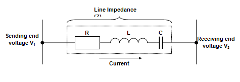
Figure 28: Simple Transmission Circuit
When no current flows in the circuit, the sending end voltage V1 must be equal to and in phase with the receiving end voltage V2. If a current now flows which lags behind the receiving end voltage V2 by 900, the current is purely inductive and only MVars are flowing from the sending end to the receiving end. To cause this current to flow, the sending end voltage E1 must be increased to overcome the impedance voltage drop of the circuit (IZ), as shown in Figure 29.
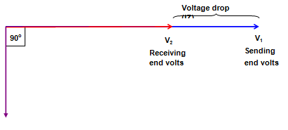
Figure 29: Requirement for Transmission of MVars
Assume now that the current is in phase with the receiving end voltage (i.e. unity power factor load), so that only MWs are being transmitted over the line. For this condition, the sending end voltage must be advanced in phase with respect to the receiving end voltage by a certain angle (d), while the magnitude of the two voltages remains practically the same. This is shown in Figure 30.
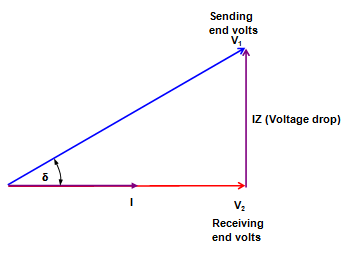
Figure 30: Requirement for Transmission of MWs
A generator supplying the system can be represented by Figure 31 in which V1 is the generated voltage, XS is the synchronous reactance and V2 is the terminal voltage. A generator is therefore similar to the simple transmission system represented in Figure 30.
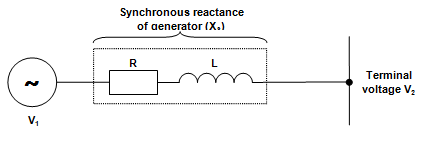
Figure 31: Electrical Circuit of a Generator
It can be seen that for all practical purposes:
• The reactive (MVar) component of the current flowing depends only on the magnitude of the generated and terminal voltages.
Increasing the energy input to a generator causes the generated voltage to momentarily advance on the terminal voltage, increasing the rotor angle and consequently increasing the MWs generated.
Increasing the excitation of a generator increases the magnitude of the generated voltage, and consequently the terminal voltage and the MVar output is increased.
Division of MW Load Between Generators
Control must be exercised over the division of the system MW load between the generators so that each generator carries its optimum load for maximum efficiency. This is achieved by adjustment to the governor speeder gear, either manually or automatically under the control of the automatic frequency control system. The provision of the speeder gear also permits the load on any generator to be varied from zero to full load without a change in speed and this enables generators to be placed in and out of service on a system of constant frequency.
Should the system load change, resulting in a change in frequency, each generator will automatically pick up or reject load through the action of its governor. In this way, the frequency automatically is restored close to its original value; the difference between the new frequency and the original frequency, or offset, is due to the proportional characteristic of the governors. This is then corrected by appropriate adjustments to the speeder gears on selected units.
For a change in frequency, it is necessary that each generator pick up or reject load in proportion to its rating, to prevent the possibility of some generators becoming overloaded while others remain loaded below their MCR. This requires that each governor have the same droop characteristic of its speed-load curve, and in this way, changes in the system load are automatically shared equitably between the generators.
Figure 32 shows the speed-load curves for a 600 MW unit and a 400 MW unit, both curves having the usual 4% droop or speed regulation. Assume both generators are supplying a total load of 500 MW at 50 Hz and that the 600 MW unit has a load of 300 MW and the 400 MW unit has a load of 200 MW. It can be seen that if the system load now increases so that the frequency falls 1% then each generator will automatically assume 75% of its full rated output. The 1% drop in frequency can be corrected by operation of the speeder to increase the output of the units. This action raises the position of the speed-load curves so that the units then operate on a higher curve parallel to the original.
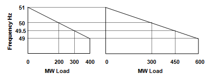
Figure 32: Governor Speed-Load Curves
Division of MVar Load Between Generators
We learnt earlier that the power factor of a generator operating alone was determined by the power factor of the load and this in turn determined the MVar load on the generator. When the generator is operating in parallel with others this restriction does not apply and the power factor and MVar load on the generator can be varied at will by varying its excitation.
It is desirable that the MVar demand of the load connected to the power station busbars should be distributed amongst the generators so that the ratio of MVar load to MW load is the same on each generator. This division of MVar load is to eliminate the circulating current which otherwise would flow between the generators.
Circulating Current Between Generators
Assume that a generator has just been synchronised to the busbars and that its terminal voltage and frequency are now held constant. If the excitation is increased, the following effects will occur:
• The generator ammeter will increase almost proportionally to the increase in excitation;
• The MW meter will show practically no reading;
• The power factor meter will show a highly lagging reading;
• The MVar meter will indicate a large export of MVars.
The result of increasing the excitation is to cause a reactive current, practically lagging 90o behind the terminal voltage, to flow in the highly inductive generator circuit. This reactive current circulates in the local circuit between the various generators connected to the busbars and does not enter the external load circuit; it is therefore called a circulating current.
A circulating current increases the heating of the generator, increases losses, and decreases the current the generator can supply to the load circuit, since the stator current is made up of the vector sum of the load current and the circulating current.
Division of MVar Load to Eliminate Circulating Current
The circulating current is eliminated when each generator has its excitation adjusted so that each operates at the same power factor, which will be that of the load connected to the busbars. This means that the ratio of MVar to MW load should be the same on each generator and that the same ratio applies also to the load connected to the busbars.
For example, if two generators operating in parallel are supplying a total load of 800MW, 160 MVar and the generator loads are 500 MW and 300MW then the excitation should be adjusted so that the first carries 100 MVar and the second, 60 MVar.
Because the voltage-load characteristic often differs between generators, a change in MW load will generally require a re-adjustment of the excitation to restore the correct division of the MVar load. For this reason, compounding circuits are frequently provided on the voltage regulators, which automatically assist in maintaining the same power factor on generators operating in parallel and consequently the correct division of reactive loading.