Introduction to Generator I
2. Principle of Generators
The basic principle of a generator is a magnetic field and an armature assembly with relative motion between the two. Either the magnetic field or the armature may be rotated to produce the electromotive force (emf). Electromotive force is the voltage produced and is measured in volts.
In modern generators it is more practical to rotate the magnetic field (known as the 'rotor') as it is smaller in size, has only two sliprings and operates at a lower voltage therefore requiring less electrical insulation. The armature assembly constructed of a large magnetic iron core and windings (conductors) is the stationary component of the generator and is called the 'stator'.
Small generators usually employ permanent magnets for the magnetic field poles while high output generators will require electromagnetic field poles. The electromagnetic field used in power station generators is constructed of an iron core with wound coils and when direct current (dc) is passed through the coils a magnetic field is created within the iron core causing it to become a magnet.
Electromagnetic Induction
Voltage is induced in a conductor when there is relative motion between that conductor and the lines of force of a magnetic field. The voltage produced is referred to as electromotive force (emf) and is the result of the principle of electromagnetic induction.
The production of an emf by electromagnetic means is the sole purpose of a generator. To achieve this, foundations for the generator design must be developed from the fundamental principles of electromagnetic induction.
For the production of a voltage by electromagnetic means there are three fundamental requirements:
• Magnetic field within the locality of the conductor;
• Relative motion between the conductor and the magnetic field.
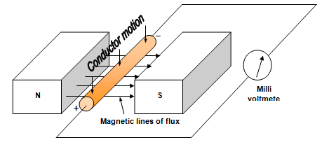
Figure 1 shows all three requirements for the production of an emf.

Figure 1: Conductor Moving Down Through a Magnetic Field
The Simple Generator
There are two different designs for generators:
• Rotating field construction.
Figure 2 shows the two different designs for the simple generator. They are both single phase generators; three phase generation will be discussed later in this module.


Figure 2: Two Designs for Simple Generator
In Figure 2(a) the conductor loop is rotated through a magnetic field cutting the magnetic lines of flux. In Figure 2(b) the magnetic field is rotated within the stationary conductor loop causing the magnetic lines of flux to be cut. With both designs the emf is induced in the conductor loop.
Even though the simple rotating field type is the preferred construction for power station generators the rotating armature was the first implemented and we will use it to describe the principles of electromagnetic induction.
Principles of Electromagnetic Induction through the Rotating Armature
When the conductor loop is rotated within the magnetic field of the permanent magnet poles an emf is induced into that conductor loop. A sliding electrical connection is provided in the form of sliprings and carbon brushes to provide a path to and from the external circuit. Individual sliprings are connected to opposite sides of the conductor loop.
If we refer to Figure 2 and use Fleming's right-hand rule for generators it can be shown that:
• Each side of the loop changes the polarity of the emfs that are induced into each half cycle (180 degrees) of rotation;
• Each side of the loop has the induced emf polarities reversed each time they reverse the direction in which they cut the magnetic flux;
• Each side of the loop changes the direction in which it cuts the magnetic flux twice for each revolution – for one half of the cycle it cuts the flux upwards while for the other half it cuts the flux downward.
Note: The sum of the voltages induced into the loop is twice that of a single conductor as the loop is essentially two conductors connected in series, with the instantaneous voltage of each conductor being of equal magnitude and of opposite polarity.
Generation and Magnitude of an AC Sine Wave
With the resultant emf changing direction twice for each 360 degrees of rotation the generated voltage and consequently the output from the sliprings takes the form of and alternating current (AC).
To calculate the magnitude of an emf induced in a conductor cutting a magnetic field of constant flux density at right angles to the flux we use the equation:
e = Blv
Where:
e = instantaneous emf [in volts (V)]
B = strength of the magnetic field [in teslas (T)]
l = active length of conductor (conductor under the influence of the magnetic field) [in metres (m)]
v = velocity of the conductor [in metres/second (m/s)]
Emf's can be induced into a conductor to produce a sine wave if rotation is circular and the density of flux is distributed uniformly. Figure 3 illustrates the production of a single phase sine wave through one complete cycle of a simple two pole generator.
The five instances (a-e) shown in Figure 3 indicate:
• value of emfs that will be induced within the loop after it has rotated through a particular angle.
The sections represent:
a) 0 volts at 0o of rotation
b) e maximum (positive) at 90o of rotation
c) 0 volts at 180o of rotation
d) e maximum (negative) at 270o of rotation
e) 0 volts at 360o of rotation
In each of the sections there are four illustrations; these indicate:
I) position of the loop within the magnetic field.
ii) front cross-sectional view of the loop within the magnetic field.
iii) angle or portion of a revolution in degrees that the loop has rotated within the magnetic field.
iv) direction and the relative magnitude of induced instantaneous emf’s that have occurred at each instant between the start of the loops rotation and its present position.

Figure 3: Single Phase Sine Wave Alternation
Description of Sine Wave Production
A circular path is continually repeated by the loop as it cuts the flux during its rotations within the magnetic field; in this instant it rotates in a clockwise direction. As a result of the path being circular, at each instant of its rotation it will cut the flux at a different angle. Consequently, when the loop moves through the magnetic field at a constant velocity cutting the flux, the rate at which flux will be cut will vary with the size of the angle.
The sine wave is the required output wave form, the name being derived from its sinusoidal shape. To achieve this waveform each side of the loop has to cut the flux at a rate which conforms to sine law. So, the resultant ac waveform is composed of an infinite number of instantaneous values of induced emf with magnitude proportional to the sine of the angle.
The maximum rate of flux change will occur at those angles whose sine = 1 or -1 for each revolution that the loop rotates. Within a two pole field these angles are 90 and 270 degrees.
When either side of the rotating loop cuts the flux at angles of 0, 180 and 360 degrees within the same field system it moves parallel to the lines of force. Ideally, zero flux is cut, resulting in zero induced emf. At other angles the instantaneous value of emf will achieve a magnitude somewhere between zero and maximum in either the positive or negative direction. Each individual magnitude will depend upon the angle at which each side of the loop cuts the flux, and it will be proportional to the sine of the angle.
As a result of the loop rotating in a circular motion within this magnetic field each instantaneous emf (e) induced in each side of a loop is not only dependent an BIv, it is also proportional to the sine of the angle of intersection between the conductor and the flux (sinθ) (θ is the Greek term 'theta' and is used in electrical as referring to angular). As a consequence of this the induced instantaneous emf can now be calculated from the equation e = Blv sinθ.
Calculation of Instantaneous Voltages
Remembering that maximum emf is induced when a conductor is being cut at 900. As the conductor is not always moving at 900 to the magnetic field then maximum emf will not always be produced. Thus giving rise to an expression of voltage:
e = Blv sinθ
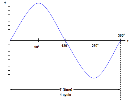
Where sin θ is the degree of rotation through the magnetic field as shown in Figure 4.

Figure 4: Sine Wave
The value of induced emf compared to the maximum value is calculated by multiplying the maximum value by that fraction of the rotating motion that is the horizontal component.
This fraction is equal to the sine of the angle through which the conductor has rotated.
The calculation of the instantaneous value of voltage or current uses the expression:
e = Vmax sin θ (volts)
Where:
e = the instantaneous voltage in volts
Vmax = maximum voltage in volts (peak voltage)
θ (theta) = angle of rotation in degrees
or
i = Imax sin θ (amps)
where:
I = the instantaneous current in amps
Imax = maximum current in amps (peak amps)
θ (theta) = angle of rotation in degrees
These values may be expressed in either a positive or negative value.
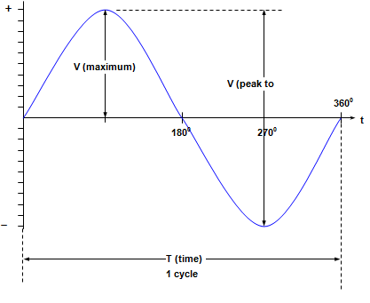
Alternating Waveform Quantities
• Peak to peak voltage
• Cycle
• Period (time taken to complete one cycle)
• Frequency (number of cycles per second)
All these quantities are shown in Figure 5.

Figure 5: AC Quantities
Expressions relating to time and frequency
T = 1/f
or
f = 1/T
Where:
f = frequency (in Hertz or cycles per second)
T = time (in seconds)
