Introduction to Generator I
4. Generator Construction
The main features of the generator are a rotor surrounded by a two part stator, rotor current collecting rings, known as slip rings, and an assembly of bushings forming the output voltage terminals.
Six high voltage bushings are attached, through terminal plates, to a terminal box located on the underside of the generator collector end. These bushings provide the means for the generator to be electrically connected to the external buses. Each high voltage bushing is internally cooled by the circulation of hydrogen gas.
End shields at either end of the generator stator are of gas tight construction and support the generator bearings and shaft seals which prevent hydrogen gas leaking from the generator.
The entire assembly is gas tight to allow hydrogen gas to be forced through the internal parts for cooling. The stator windings are also cooled by demineralised water.
The generator is of the conventional form for large power stations, with an inner rotating two-pole field and outer fixed conductors. The rotating field is D.C. excited from a static thyristor excitation system.
Excitation current is supplied to the field windings of the rotor from the collector rings. Two semi-circular conductors run through the drilled-out centre of the rotor forging to connect the collector rings with the field windings.
There are four hydrogen coolers, one vertically mounted at each corner of the generator stator.
Resistance Temperature Detectors (RTD’s), thermocouples and stator liquid drains are positioned within the generator assembly for monitoring generator operation.
Current transformers encircle the six individual high voltage bushings to measure the amount of current supplied by the generator and provide protection for the generator. The output of each current transformer is monitored in the Unit Control Room (UCR).
Rotor Cylindrical Construction
Steam turbines operate with greater efficiency when operated at higher speeds. This requirement for a high speed rotor that could handle the greater centrifugal forces led to the introduction of a small diameter cylindrical rotor. As the diameter of the rotor was reduced the length of the rotor had to be increased to maintain the same electrical output.
This cylindrical rotor is constructed as a single forged alloy steel casting into which are machined deep axial slots. These axial slots run the entire length of the rotor and accommodate the rotor windings. A diagram of a rotor forging without any winding conductors is shown in Figure 8.
The winding conductors usually made up of continuous copper strip are insulated and formed into a number of oblong frames of suitable dimensions. Once formed they are laid into the machined slots and then retaining wedges or dovetail keys are driven in from either end to prevent the winding from exiting the shaft when subjected to centrifugal force. Figure 9 shows an enlarged view of a single machined slot with the winding conductor inserted and the retaining wedge installed.
Once the conductors are installed connections to complete the winding are carried out at each end with the start and finish tails being brought out to the sliprings. A cylindrical rotor with rotor windings installed is shown in Figure 10.
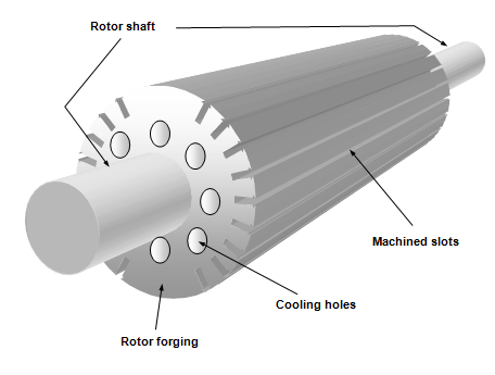
Figure 8: Cylindrical Rotor Forging
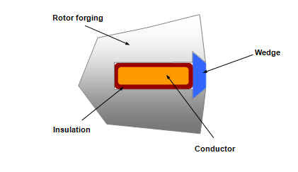
Figure 9: Rotor Machined Slot with Conductor and Retaining Wedge Inserted
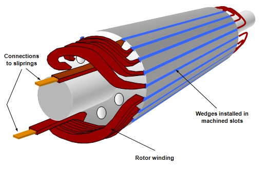
Figure 10: Cylindrical Rotor with Rotor Winding Installed
The rotor windings are suitably supported within the rotors machined slots by the retaining wedges but the section of winding that protrudes each end of the rotor forging need also to be supported. This is achieved by the shrink fitting of retaining end covers or more commonly called end bells. These end bells are normally manufactured from non-magnetic alloy steel and during operation are subjected to high stresses. Dovetail groves are often machined into the ends of these end shields for the provision of counterweights. A rotor showing the end bells installed is shown in Figure 11.
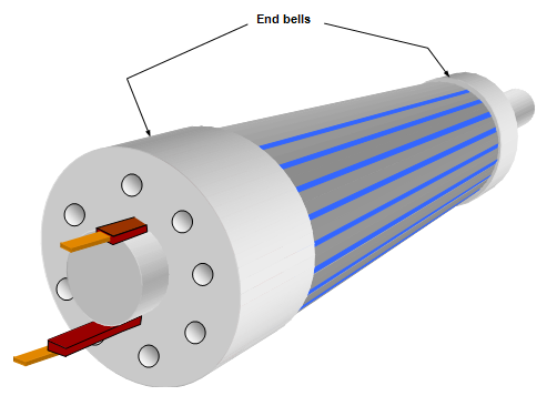
Figure 11: Cylindrical Rotor with End Bells Fitted
Apart from the rotor being constructed of the forging, windings and end bells it also has a shaft with a series of stepped diameters to accommodate:
• Journal surfaces for gas seals;
• Coupling for turbine drive and exciter drive shaft;
• Sliprings;
• Journal surfaces for bearings.
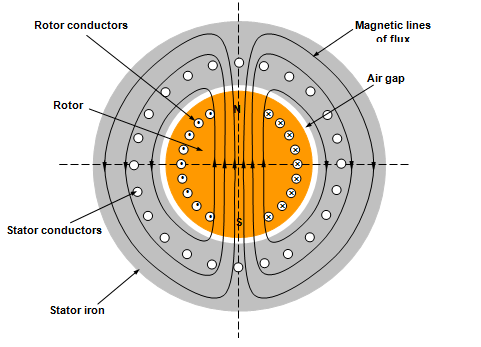
Figure 12: Magnetic Flux Path through Generator
Rotor Cooling
Heat is generated in the windings of the rotor as the dc excitation current flows through the conductors. This heat must be removed because of the temperature limits imposed by the insulating material surrounding these conductors. For this reason and to achieve a high output with a relatively compact machine a forced cooling system is adopted. This forced cooling system may employ air for small output generators or hydrogen for larger generators.
Whether the cooling medium is air or hydrogen the heat extraction process is the same. Cooled air/hydrogen is forced around the outer surface of the rotor as well as through the holes machined in the rotor casting and end bells.
Fan blades installed on the shaft or at the outer ends of the end bells force the cooled air/hydrogen through the rotor where it absorbs heat. The cooling air/hydrogen is then ducted to coolers where the unwanted heat is extracted before it is once again passed through and around the rotor.
Rotor Excitation
The excitation system is the means we use to regulate the voltage output of the generator. When a generator is connected to a large electricity grid and operating in parallel with a number of other generators a variation in the excitation which causes an increase or decrease in rotor field current causing a change in MVar or reactive power output of the generator. Provided normal excitation conditions are established the megawatt or real power output of a generator is entirely dependent on the input power to the steam turbine (i.e. steam conditions)
Excitation current is regulated to maintain a generator terminal voltage to suit power distribution system requirements under changing conditions.
The excitation system consists of a number of components:
• Automatic voltage regulator;
• Rectifier/s;
• Main exciter;
• Sliprings;
• Rotor field.
The excitation system starts with the pilot exciter which usually has a permanent magnet rotor. In some cases the pilot exciter has an electromagnet type rotor which is excited with dc from the station batteries.
The pilot exciter is connected to the same shaft as the main exciter and generator and this can be seen in Figure 13. This common shaft is rotated at 3000 rpm for 50Hz output and 3600 rpm for 60Hz output.
The electrical current produced by the pilot exciter is passed through the automatic voltage regulator (AVR). The AVR regulates the input excitation to the main exciter depending on generator output demands. Output from the main exciter is then rectified prior to being passed through the sliprings and into the rotor windings.
The AVR is installed in the system immediately after the pilot exciter as lower currents are present at this location and therefore permitting the AVR to be a cheaper and more compact unit.
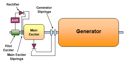
Figure 13: Simplified Diagram of Excitation System
Automatic Voltage Regulator (AVR)
The AVR is the device that regulates the terminal voltage of the generator. It can be operated in manual control (not recommended and only used in emergency) and fully automatic control (preferred mode).
There are a number of different methods employed to carry out the function of the AVR but the result is the same for each case. A simplified method of operation is shown in Figure 14.
The operating principle of the AVR shown in Figure 14 is as follows:
The electrical output from the pilot exciter is firstly rectified. It is then passed through the resistance bank and beam balance to the positive slipring of the main exciter. The negative slipring is connected directly back to the pilot exciter.
As the terminal voltage of the generator increases the voltage sensed by the VT increases. This causes the current flowing through the beam balance operating coil also to increase. With this increase in current in the operating coil the magnetic strength increases and attracts the beam balance towards it. As this happens the contacts on the beam balance move in a clockwise direction to the next terminal thus increasing the resistance in the circuit to the main exciter sliprings. This causes a reduction in excitation strength to the main exciter and then the generator rotor, which, in turn, reduces the generator terminal voltage.
Conversely if the generator terminal voltage falls the operating coil has less magnetic attraction and the beam balance moves in an anti-clockwise direction under the influence of the spring attached to the beam balance. The causes the beam balance contacts to move to the next terminal and reduce the resistance in the circuit. With this reduction in circuit resistance the circuit current increases causing an increase in excitation in the main exciter and generator rotor causing the generator terminal voltage to rise.
After either an increase or decrease the system will find a point of equilibrium and remain at that point unless the generator terminal voltage is changed by system requirements or adjustment of the set point.
The set point for generator voltage is adjusted on this system is by rotating the knurled knob to either increase or decrease spring tension on the beam balance.
This explanation of how an AVR operates is an exceptionally simple one and is not used on modern generators but the principle is the same. Modern AVR’s are fully electronic and have increased features and redundancy incorporated into them for greater reliability.
Figure 14: Simplified AVR
A later trend in excitation control is to eliminate the pilot exciter and main exciter completely and substitute these with a static excitation system consisting of an excitation transformer, automatic excitation regulator (AER), pulse amplifier (PA) and thyristor rectifier. A simplified diagram of this system is shown in Figure 15.
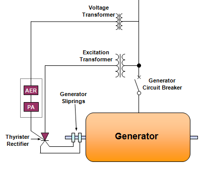
Figure 15: Simplified Diagram of an Automatic Excitation Regulator
The advantage of this system is that it is cheaper and has no moving part; but the disadvantage with is that excitation power must come from the electrical grid and therefore black start ability is not available.
Brushless Excitation
Some generator manufacturers offer a brushless excitation system. A diagram of this system is shown in Figure 16 and a description of operation follows.
With brushless excitation the pilot exciter is a normal permanent magnet rotor construction. The AVR is installed in the same location as for slipring construction but the main exciter is constructed with the main field as the stator and a three phase wound rotor. Installed in the shaft is a set of rectifiers that supply the generator rotor with dc excitation.
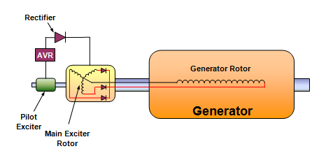
Figure 16: Brushless Excitation
Stator Construction
The stator of a large modern generator is constructed of three main components:
• Iron Core
• Windings
Outer Frame
The outer frame is of welded steel plate construction. It is rolled and welded to form a cylindrical shape and is gas tight. Depending on whether the generator is either hydrogen or air cooled will determine the actual construction strength. For air cooled generators a lighter construction is employed as this type of generator only operates slightly above atmospheric pressure where as a hydrogen cooled generator operates at 300-400kPa above atmospheric pressure. The construction technique is the same for both only more robust for hydrogen cooled generators to accommodate the greater pressure. A diagram of an alternator stator is shown in Figure 17.
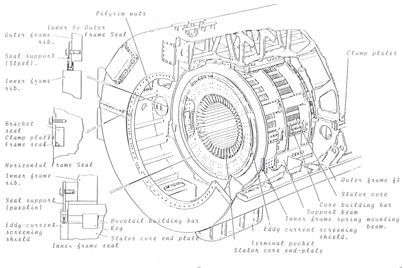
Figure 17: Outer Frame of a Generator
Iron Core
The iron core contains the stator windings (conductors) and is of laminated construction. A number of thin (approximately 0.5mm) high quality silicon steel laminations are assembled together to form a segment. Many segments separated by spacers (to allow for cooling) are then tightly clamped together with end plates to complete this iron core. The clamping end plates are of a non-magnetic construction so as not to become part of the flux path.
Attachment of the iron core to the outer frame is by means of spring plates. These spring plates dampen out frequency vibrations generated in the iron core being transmitted to the outer frame.
Windings
Insulated stator conductors are tightly packed into the longitudinal slots of the laminated iron core and secured with wedges. Overhanging coil ends are lashed down with insulating material to insulating blocks bolted to the iron core end plates.
Both ends of each phase of the stator windings are brought out to the generator terminals, which can be situated on either the top or bottom of the outer casing (depending on manufacturer). Three of these terminals form the three phase conductors that connect to the generator transformer. The other three terminals are connected together to form the neutral or star point of the generator.
The stator conductors are formed into a coil to make up each phase and can be either solid construction (low output generators) or of the hollow tube construction (high output generators). A solid type construction is shown in Figure 18 while a hollow tube type is shown in Figure 19.
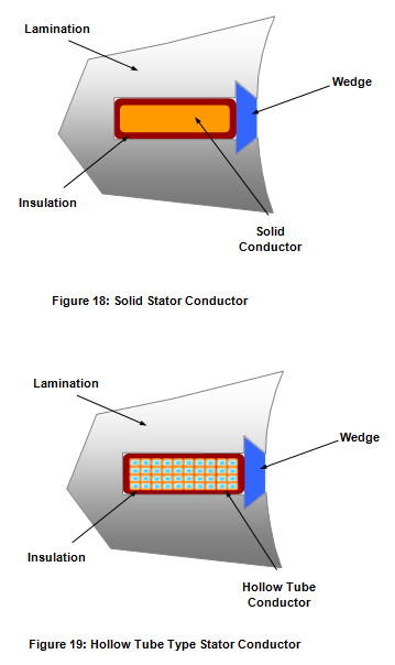
The benefit of a hollow tube type conductor is that a cooling fluid can be passed through the centre of the individual conductor to remove unwanted heat. With this type of construction the physical size of the generator can be greatly reduced whilst maintaining the megawatt output.
Bearings and Lubrication
The rotor shaft is supported by two white metal journal bearings similar to that used on the turbine rotors. These horizontally mounted bearings are of a split type construction and bolted to the endplates of the outer casing. All joints are gas tight and the bearings are insulated to stop the flow of induced shaft current through the bearing surfaces. If these induced shaft currents were allowed to flow through the bearing faces they would be extensively damaged by pitting caused by electrical arcing.
Lubricating oil for the bearings is supplied from the turbine lubricating oil system and jacking oil systems. For more information about these systems refer to the turbine manual of this series.
Prior to placing the generator and turbine on turning gear the rotor must be lifted by the jacking oil system to create a layer of oil sufficient to prevent any contact between the white metal bearings and the rotor shaft. For more information about this system refer to the turbine manual of this series.
The exciter and pilot exciter bearings also receive lubricating oil from the turbine lubricating oil system but are not supplied with jacking oil due to their significantly lighter construction.
