Introduction to Generator I
6. Generator Capacity or Performance Diagram
When operating a generator we must consider conditions which impose limits on the loading of the generator. Information is often provided in the form of a tabulation which gives for instance permissible megavar (MVar) loading for a particular megawatt (MW) load on the generator. In is however more convenient to provide this information in the form of a generator capability performance diagram.
The conditions that impose limits on generator loading and the reason for the limit are shown in Table 2 below.
|
Limiting Condition |
Reason for Limit |
|
Stator current MW Load Rotor angle Rotor current |
Stator temperature rise Turbine characteristics Generator stability Rotor temperature rise |
A complete capability diagram will now be developed by considering in turn each of the operating limits described in Table 2.
Multiplying stator current by rated generator voltage gives us a mega volt-ampere (MVA) limit for the generator. This information is diagrammatically shown in Figure 23 which is known as a simple circle diagram for a generator.
The diagram shown in Figure 42 can also be considered as a generator capability or performance diagram which in this instance only takes into account the stator current or MVA limit and ignores all other operating limits imposed on the generator. Provided that the MW and MVar load on the generator coincides with a point falling anywhere within the confines of the diagram the stator current (and MVA) limit of the generator will not be exceeded for normal rated voltage conditions.
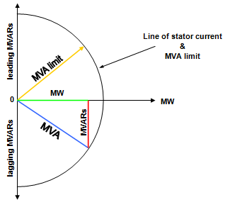
Figure 23: Generator Capability Diagram (showing MVA & stator current limit only).
Figure 24 shows the generator capability diagram now modified to take into account the MW load limit due to the power available from the turbine.
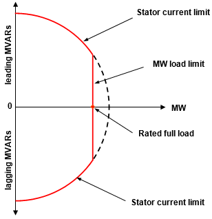
Figure 24: Generator Capability Diagram (showing stator current and MW load limits).
Rotor angle and stability limit is reached only when the generator is operating at a leading power factor and importing MVars. This theoretical stability limit corresponding with a rotor angle of 90o is now incorporated and shown in Figure 25. The limiting value of leading MVars for a rotor angle of 90o depends on the design of the generator but is usually around two thirds of the maximum MW load (i.e. a 60 MW generator would have a MVar capability of approximately 40MVars).
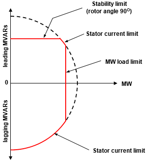
Figure 25: Generator Capability Diagram (showing stator current, MW load and stability limits
The final limiting condition to be considered is rotor current limit. Rotor current limit is reached when the generator is producing considerable MVars to supply a lagging power factor and under these conditions rotor excitation is at a high level. Figure 26 shows a capability diagram in which there is a small area where the limiting factor is stator current but a large area relating to rotor current limit. With some generators there is no stator current limit when the machine is operating on high excitation and this is shown in the capability diagram of Figure 26.
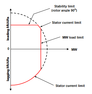
Figure 26: Generator capability diagram (showing the four limiting conditions).
The capability diagram of a typical 60MW generator is shown in Figure 26 Lines are drawn on the diagram showing rotor angle and power factor for various loading conditions for the generator. Also shown are three stability limits; one for when the excitation is on automatic voltage control (AVR) which permits operation beyond the theoretical stability of 90o, one showing the theoretical stability limit and the other for when the excitation is on hand control and it is necessary to incorporate a stability margin of safety.
In Figure 27 it can be also seen that the stator current limit is reached only at high leading MVar loads and that the rotor current limit is the only restriction on lagging MVar loads.
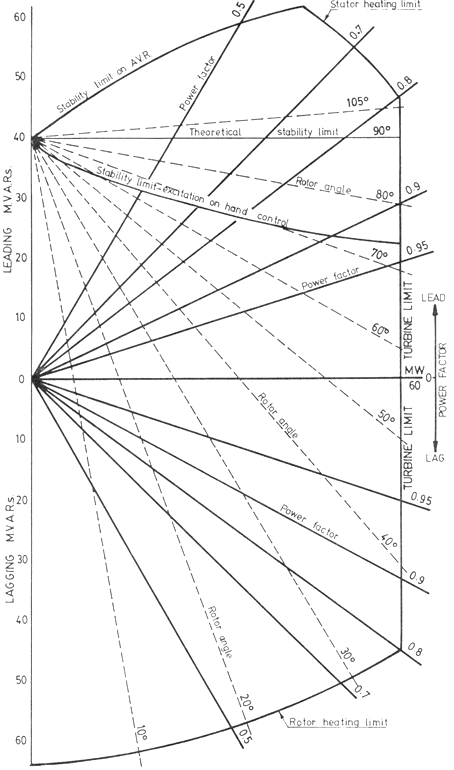
Figure 27: Capability Diagram for a 60MW Generator.
It should be remembered that the limiting conditions shown on a capability diagram apply only for normal rated voltage.
While the capability diagram is a useful guide to generator operation (particularly in the leading power factor region), it is important that full reliance should be place on the available generator instruments such as ammeters, rotor angle indicator, temperature indicators and alarms to ensure that specified limits are not exceeded.
