Introduction to Generator I
7. Synchronising and Parallel Operation of AC Generators
Control of the Generator Preparatory to Synchronising
There are several requirements that must be satisfied before a unit can be synchronised to the system.
They are:
• Phase angle between the incoming generator and the system must be matched;
• Frequency of the incoming generator and system must be the same;
• Incoming and system must have the same phase rotation.
Operators have control of the first three of these requirement and we will now discuss these in detail.
Control of Voltage
The voltage of the incoming supply (generator terminal voltage) is regulated once the generator field switch has been closed and the excitation adjusted. The field switch is often closed during the run up period at approximately 90-95% normal rated speed. It is good operating practice to always have the excitation control system set at minimum position whenever the field switch is closed to avoid any risk of over-voltage. It is normal practice once the field switch is closed that the AVR be selected auto and the terminal voltage set point adjusted to meet synchronising requirements.
The voltage of the generator increases as the speed increases and the synchronising voltmeter should be observed to check that the AVR is maintaining the required set point value. A final adjustment of voltage may be necessary when the unit is running at synchronous speed.
NOTE: As the impedance of the generator transformer is primarily the component of inductive reactance it is critical that the speed of the machine does not go below a predetermined value as with low speed we get low frequency and this can cause overfluxing of the generator transformer. Overfluxing is when a transformer draws excessive magnetising current.
Control of Frequency and Phase Relationship
When the speed of the turbine is within range of the governor, the frequency of the incoming supply can be regulated on the speeder gear. The speeder gear should have been set to minimum before the run‑up so that control can usually be exercised once the speed exceeds approximately 2850 rpm.
When the generator is running close to normal speed as indicated on the tachometer or frequency indicator or recorder, the synchroscope can be energised. The operating range of the synchroscope is fairly narrow and it should not be energised until the speed is close to normal. When the frequency of the generator and the system is the same, the pointer of the synchroscope will remain stationary at some point around the dial.
The phase relationship between the incoming supply and the system is varied by momentarily changing the generator frequency. If the generator is running steadily at a frequency which is close to but not quite equal to the system, the phase relation between the two will be slowly changing all the time. The synchroscope pointer will rotate at a speed proportional to the difference in frequencies, and the position at any instant indicates the instantaneous phase relationship, between the incoming supply and the system. For example, at 12 o'clock, they are in phase, at 6 o'clock, 180o out of phase.
Infinite Busbars
In some respects, a large distribution system can be considered as a large mechanical flywheel. Each generator contributes its share of energy to keep the flywheel rotating at constant speed while the electrical load on the system acts as a brake, tending to slow the fly wheel down. When the capacity of the system is very large, changes in conditions on one of the generators may have little or no perceptible effect on system conditions.
An individual generator connected to a system which in comparison may be regarded as infinitely large, is said to be operating on "infinite busbars". Such a system is essentially a source of voltage and frequency, both of which remain. substantially constant.
Except for large variations in the conditions on a generator, the state distribution system closely approaches the concept of infinite busbars. Although changes actually occur on the system when the speeder gear or excitation is varied on a generator, the effect frequently is so small that it is not noticed on the control room instruments.
For example, if a system, having multiple generating sets operating in parallel to supply a load of 8000 MW, was deprived of 350 MW to 400 MW of generation, the frequency would fall significantly by approximately 0.1 Hz. Should this reduction in generation be confined to the loss of a single generator, however, there would be only a small change in system frequency because the governors of the remaining generating units would automatically increase their output. In the same way, the AVR's on these units would automatically compensate for the lost MVar output of the lost unit so that the system voltage will remain practically unchanged.
Stable Operation of Generators Operating in Parallel
Stability
The term stability defines the ability of a generator to remain in synchronism with the power system.
The two conditions of stability are:
• Transient
Steady State Stability
The steady state stability of a generator defines its ability to remain in synchronism under conditions of steady state operation such as load drift, voltage drift and small slow low intensity load changes.
Transient Stability
Transient stability defines the ability of the generator to return to its former state of stable operation after having been disrupted due to sudden changes of loading or voltage conditions due to power system faults, large load swings or sudden tripping of sections of the power system network.
If a machine is operating with a fair margin of safety within its steady state stability limit it will rarely become unstable under transient conditions unless the disturbance is very violent and sustained such as a close up three phase fault which is also slow to clear.
If a machine is operating close to its limits of steady state stability it is less likely to be able to sustain a moderate system disturbance without falling into an unstable condition.
Transient conditions will arise if there is a sudden change in any of the quantities of this general power equation, i.e., there will be a transient disturbance if there is a sudden change in generator driving torque, excitation or load.
If a steam turbo-generator operating in parallel with other generators is subjected to a sudden load change; then that change may be either a load reduction or load increase. Since the steam governor cannot respond instantly to the load change there will be a power differential between the generator input and output and this power differential will either accelerate or decelerate the rotor from its initial steady state condition towards the new power angle required by the change in load.
There are some other methods such as increasing busbar volts or reducing the reactance of the load but these are generally outside the control of the operator.
It is not recommended that the above actions be taken once pole slipping has occurred. It is advisable to trip the unit and resynchronise under controlled conditions. For this reason most modern generators have an automatic trip once pole slip has occurred. It is therefore imperative that vigilance is exercised in preventing the generator from entering or nearing an unstable region.
Increasing Excitation
This is the simplest and quickest way of restoring stability to a generator that is approaching an instability region. This also emphasises the need to ensure that the Automatic Voltage Regulator (AVR) is selected auto whenever possible.
Decreasing Load
Reducing the steam input is also an effective action that can be adopted, but it would have to be known that a condition of instability was imminent. This is a very direct method of ensuring continued stability but takes longer to implement than excitation adjustment.
Causes of Instability
It should be noted that the effect of a downward frequency drift is perhaps one of the greatest dangers likely to lead to instability since this condition is nearly always attended by a corresponding voltage drift, also downwards. The sloping characteristic of the governor droop, which is normally 4% between no-load and full load results in an increase in the loading on the machine as the frequency sinks without the steam input being adjusted.
The combined effects of loading increase and voltage reductions can cause a deviation so far that the stability of the generator is compromised and if not arrested in time could become cumulative and result in the collapse of the total generation at a power station or even of the complete system.
It should also he noted that a frequency drift upwards has an opposite and therefore, beneficial stabilising effect.
Effect of Automatic Voltage Regulator on Generator Stability
The practical stability limit set for a generator sometimes differs when the excitation is on manual control and when it is on AVR control. This is because the action of an AVR assists considerably in maintaining generator stability and allows a higher practical stability limit to be set when the excitation is controlled by the AVR than that allowed when it is controlled manually. In fact, a modern AVR, having a high speed of response, is capable of maintaining stability under steady conditions at rotor angles as high as 120o, which is well beyond the theoretical stability limit.
Suppose for example, that, while a generator is operating under steady conditions at some point in excess of the theoretical stability limit, a disturbance causes the rotor angle to increase slightly. The consequent reduction in power output immediately tends to cause the rotor to accelerate out of step, but with the increase in rotor angle there is also a drop in terminal voltage, which is detected by the AVR. If the excitation now is rapidly boosted by the AVR, the generator will operate on a higher rotor angle and provided the new power output is greater than the original power input, the generator will slow down, reducing the rotor angle to its original value, and stability is maintained.
The greater the rotor angle exceeds 90o, the more difficult it is for the AVR to control the situation described above. This is because the slope of the curve becomes steeper as the rotor angle increases, and the speed of response of the AVR has to be correspondingly faster in order to maintain stability. Modern AVR's have a rotor angle limiter incorporated in their control circuit, which is designed to boost the excitation when the rotor angle exceeds a pre-determined value, independently of the drop in terminal voltage.
Practical Factors Relating to Generator Stability
In order to increase the stability margin of a generator, the rotor angle must be reduced. This can be achieved by increasing the excitation, whether on manual or AVR control and by reducing the MW output (by reducing the speeder gear setting). In general, increasing the excitation should be adopted in the first instance and then, if necessary, reducing the MW load.
As described previously, it is important to keep the AVR in service and on auto at all times unless it is impracticable to do so because of an AVR fault. If it is necessary to operate the AVR on manual System Control should be notified.
Effects of Excitation & Load Variation on a Generator Operating in Parallel
The electrical load supplied by a distribution system consists of two components, the active or MW component and the reactive or MVar component. The relative magnitudes of these components are primarily determined by the characteristics of the connected load, but they will vary to a certain extent with changes in the system voltage and frequency.
For example, a particular system load will demand a certain number of MWs at a certain frequency, say 50 Hz. This is determined by the load characteristic. If now, the number of MWs supplied by the generators is insufficient to meet the demand, then the frequency falls. The reduction in frequency reduces the MW demand of the load and the frequency stabilises when the reduced MW demand again balances the MW supply. Conversely, if the supply of MWs is increased, then the system frequency rises.
A similar situation exists in relation to the system voltage, in that a particular load will demand a certain number of MVars for a given voltage. Should the number of MVars supplied by the generators be insufficient to meet the demand the voltage falls and in so doing reduces the demand for MVars. Again, the system voltage stabilises when the supply of MVars is sufficient to satisfy the demand at the reduced voltage. To increase the voltage it is necessary to increase the number of MVars supplied; which balances the increased demand at the higher voltage.
The main adjustments provided on a turbine generator, namely the governor speeder gear and the excitation control, when altered on a generator operating in parallel with others, cannot alter significantly the MW and MVar components of the system load, since the system frequency and voltage remain practically constant. However, they can alter the relative magnitudes of these two components supplied by a generator. The effects of these changes will be described in the following sub-sections.
Effect of Load Variation on Generator Power Factor
The MW component of load supplied by a generator operating in parallel with others is controlled by regulating the steam input to the turbine by adjusting the governor speeder gear. With the excitation held constant while increasing the steam input causes the generator rotor to momentarily accelerate increasing the MWs generated. If the original load was inductive, the additional MW load on the generator will cause the generator power factor to become less lagging. Adjusting the speeder gear in to reduce load has the opposite effect.
Effect of Excitation Variation on Generator Power Factor
The MVar component of load supplied by a generator operating in parallel with other generators is controlled by regulating the rotor current, either manually or under AVR control.
Increasing the rotor current increases the generated voltage (the terminal voltage can only rise if it can increase the voltage at the busbars). The net effect is that the reactive component of the stator current increases resulting in an increase in the MVars supplied by the generator. This causes the power factor to become more lagging. The MWs supplied by the generator remains constant during this change since the steam input to the turbine has remained unaltered.
Effect of Load Variation on Generator Rotor Angle
Assume now that the governor speeder gear is altered to admit more steam to the turbine. The increase in power supplied to the generator will cause it to momentarily increase its speed.
The magnitude of the generated voltage remains constant (for fixed excitation) but momentarily it now has a higher frequency than the terminal voltage, and the rotor angle is increased. The power output of the generator increases until equilibrium is established between the power output and the power input.
Effect of Excitation Variation on Generator Rotor Angle
A generator operating in parallel with a system of constant frequency and constant voltage with a fixed governor setting, the average power output must remain constant.
Assume that the generated voltage is increased by increasing the excitation, and that momentarily, the generator is unable to alter its speed (and hence rotor angle) to accommodate itself to the new conditions.
Since the generated voltage has increased, the stator current has increased, so that momentarily the generator is delivering more power than it is receiving from the turbine, and it starts to slow down. The generated voltage thus reduces its lead on the terminal voltage, decreasing the rotor angle and the power output. The rotor angle continues to decrease until equilibrium is established and the generator is delivering the same power as before.
Effects of Generator Voltages on MW and MVar Loading
The effects of the generated and terminal voltages on the MW and MVar loading of a generator will be considered first in terms of a simple circuit as shown in Figure 28. The circuit represents a simple transmission system and the factors which determine the flow of MW and MVars from the sending end to the receiving end will be discussed.
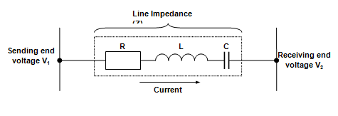
Figure 28: Simple Transmission Circuit
When no current flows in the circuit, the sending end voltage V1 must be equal to and in phase with the receiving end voltage V2. If a current now flows which lags behind the receiving end voltage V2 by 900, the current is purely inductive and only MVars are flowing from the sending end to the receiving end. To cause this current to flow, the sending end voltage E1 must be increased to overcome the impedance voltage drop of the circuit (IZ), as shown in Figure 29.
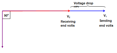
Figure 29: Requirement for Transmission of MVars
Assume now that the current is in phase with the receiving end voltage (i.e. unity power factor load), so that only MWs are being transmitted over the line. For this condition, the sending end voltage must be advanced in phase with respect to the receiving end voltage by a certain angle (d), while the magnitude of the two voltages remains practically the same. This is shown in Figure 30.
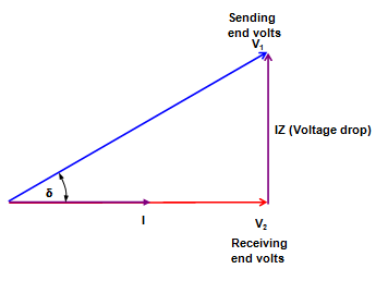
Figure 30: Requirement for Transmission of MWs
A generator supplying the system can be represented by Figure 31 in which V1 is the generated voltage, XS is the synchronous reactance and V2 is the terminal voltage. A generator is therefore similar to the simple transmission system represented in Figure 30.
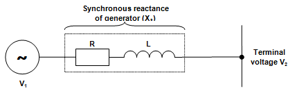
Figure 31: Electrical Circuit of a Generator
It can be seen that for all practical purposes:
• The reactive (MVar) component of the current flowing depends only on the magnitude of the generated and terminal voltages.
Increasing the energy input to a generator causes the generated voltage to momentarily advance on the terminal voltage, increasing the rotor angle and consequently increasing the MWs generated.
Increasing the excitation of a generator increases the magnitude of the generated voltage, and consequently the terminal voltage and the MVar output is increased.
Division of MW Load Between Generators
Control must be exercised over the division of the system MW load between the generators so that each generator carries its optimum load for maximum efficiency. This is achieved by adjustment to the governor speeder gear, either manually or automatically under the control of the automatic frequency control system. The provision of the speeder gear also permits the load on any generator to be varied from zero to full load without a change in speed and this enables generators to be placed in and out of service on a system of constant frequency.
Should the system load change, resulting in a change in frequency, each generator will automatically pick up or reject load through the action of its governor. In this way, the frequency automatically is restored close to its original value; the difference between the new frequency and the original frequency, or offset, is due to the proportional characteristic of the governors. This is then corrected by appropriate adjustments to the speeder gears on selected units.
For a change in frequency, it is necessary that each generator pick up or reject load in proportion to its rating, to prevent the possibility of some generators becoming overloaded while others remain loaded below their MCR. This requires that each governor have the same droop characteristic of its speed-load curve, and in this way, changes in the system load are automatically shared equitably between the generators.
Figure 32 shows the speed-load curves for a 600 MW unit and a 400 MW unit, both curves having the usual 4% droop or speed regulation. Assume both generators are supplying a total load of 500 MW at 50 Hz and that the 600 MW unit has a load of 300 MW and the 400 MW unit has a load of 200 MW. It can be seen that if the system load now increases so that the frequency falls 1% then each generator will automatically assume 75% of its full rated output. The 1% drop in frequency can be corrected by operation of the speeder to increase the output of the units. This action raises the position of the speed-load curves so that the units then operate on a higher curve parallel to the original.
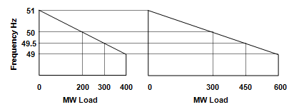
Figure 32: Governor Speed-Load Curves
Division of MVar Load Between Generators
We learnt earlier that the power factor of a generator operating alone was determined by the power factor of the load and this in turn determined the MVar load on the generator. When the generator is operating in parallel with others this restriction does not apply and the power factor and MVar load on the generator can be varied at will by varying its excitation.
It is desirable that the MVar demand of the load connected to the power station busbars should be distributed amongst the generators so that the ratio of MVar load to MW load is the same on each generator. This division of MVar load is to eliminate the circulating current which otherwise would flow between the generators.
Circulating Current Between Generators
Assume that a generator has just been synchronised to the busbars and that its terminal voltage and frequency are now held constant. If the excitation is increased, the following effects will occur:
• The generator ammeter will increase almost proportionally to the increase in excitation;
• The MW meter will show practically no reading;
• The power factor meter will show a highly lagging reading;
• The MVar meter will indicate a large export of MVars.
The result of increasing the excitation is to cause a reactive current, practically lagging 90o behind the terminal voltage, to flow in the highly inductive generator circuit. This reactive current circulates in the local circuit between the various generators connected to the busbars and does not enter the external load circuit; it is therefore called a circulating current.
A circulating current increases the heating of the generator, increases losses, and decreases the current the generator can supply to the load circuit, since the stator current is made up of the vector sum of the load current and the circulating current.
Division of MVar Load to Eliminate Circulating Current
The circulating current is eliminated when each generator has its excitation adjusted so that each operates at the same power factor, which will be that of the load connected to the busbars. This means that the ratio of MVar to MW load should be the same on each generator and that the same ratio applies also to the load connected to the busbars.
For example, if two generators operating in parallel are supplying a total load of 800MW, 160 MVar and the generator loads are 500 MW and 300MW then the excitation should be adjusted so that the first carries 100 MVar and the second, 60 MVar.
Because the voltage-load characteristic often differs between generators, a change in MW load will generally require a re-adjustment of the excitation to restore the correct division of the MVar load. For this reason, compounding circuits are frequently provided on the voltage regulators, which automatically assist in maintaining the same power factor on generators operating in parallel and consequently the correct division of reactive loading.
